Sound Signal Circuit between Headphone Terminal and Television Display
Circuit diagnosis · Vehicles built from Jan 2012
Versions by build date: Sep 2011 – Dec 2011 from Jan 2012
DESCRIPTION
This is the sound signal circuit from the television display assembly to the headphone terminal.WIRING DIAGRAM
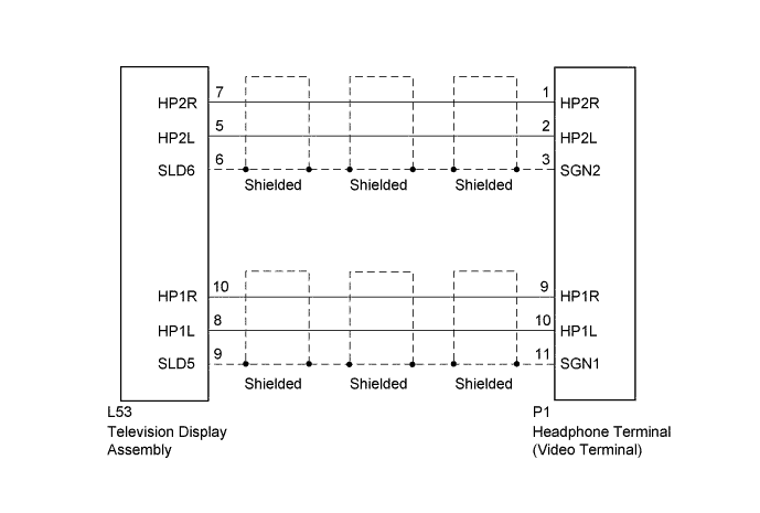

INSPECTION PROCEDURE
| 1. CHECK HARNESS AND CONNECTOR (TELEVISION DISPLAY ASSEMBLY - HEADPHONE TERMINAL) |

Disconnect the L53 television display assembly connector.
Disconnect the P1 headphone terminal (video terminal) connector.
Measure the resistance according to the value(s) in the table below.
- Standard Resistance:
Tester Connection
Condition
Specified Condition
L53-7 (HP2R) - P1-1 (HP2R)
Always
Below 1 Ω
L53-5 (HP2L) - P1-2 (HP2L)
Always
Below 1 Ω
L53-6 (SLD6) - P1-3 (SGN2)
Always
Below 1 Ω
L53-10 (HP1R) - P1-9 (HP1R)
Always
Below 1 Ω
L53-8 (HP1L) - P1-10 (HP1L)
Always
Below 1 Ω
L53-9 (SLD5) - P1-11 (SGN1)
Always
Below 1 Ω
L53-7 (HP2R) - Body ground
Always
10 kΩ or higher
L53-5 (HP2L) - Body ground
Always
10 kΩ or higher
L53-6 (SLD6) - Body ground
Always
10 kΩ or higher
L53-10 (HP1R) - Body ground
Always
10 kΩ or higher
L53-8 (HP1L) - Body ground
Always
10 kΩ or higher
L53-9 (SLD5) - Body ground
Always
10 kΩ or higher
|
|
||||

| OK | ||
 |
||
| ||