Power Seat Position is not Memorized
Circuit diagnosis · Vehicles built Sep 2011 – Dec 2011
Versions by build date: Sep 2011 – Dec 2011 from Jan 2012
DESCRIPTION
When the seat memory SET switch and a seat memory switch (seat memory switch 1, seat memory switch 2 or seat memory switch 3) are pressed simultaneously, the outer mirror control ECU commands the position control ECU and switch through CAN communication to record each position value.WIRING DIAGRAM
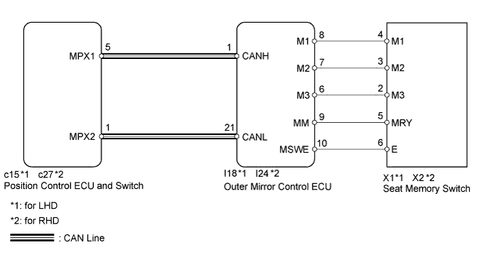

INSPECTION PROCEDURE
- NOTICE:
- First perform the communication function inspections in How to Proceed with Troubleshooting to confirm that there are no CAN communication malfunctions before troubleshooting this symptom.
| 1. CHECK FRONT POWER SEAT CONTROL FUNCTION |

Check that each function of the power seat operates normally by using the front power seat switches.
- OK:
- Each function of power seat operates normally by using seat switches.
|
|
||||

| OK | |
 |
| 2. CHECK SEAT MEMORY SWITCH FUNCTION |
Perform a memory operation properly. Check that the buzzer sounds to indicate the completion of the memory operation.
- NOTICE:
- The seat position will not be recorded if the seat memory SET switch and 2 or more of the seat memory switches (for example, seat memory switch 1 and seat memory switch 2) are pressed simultaneously.
- If a memorizing operation has failed, release all switches. The seat memory function does not operate unless the switches are released.
- The seat position will not be recorded if the seat memory SET switch and 2 or more of the seat memory switches (for example, seat memory switch 1 and seat memory switch 2) are pressed simultaneously.
- OK:
- Seat memory switch function operates normally.
|
|
||||

| OK | ||
 |
||
| ||
| 3. CHECK COMBINATION METER FUNCTION |
When the engine switch is on (IG) and the shift lever is in P, check that the combination meter shows that the shift lever is in P.
- OK:
- Meter shows that shift lever is in P.
|
|
||||
| OK | |
|
| 4. READ VALUE USING INTELLIGENT TESTER (SEAT MEMORY SWITCH) |
Check the Data List for proper functioning of the seat memory switch.
Driver Seat Tester Display
Measurement Item/Range
Normal Condition
Diagnostic Note
SET Switch
Seat memory SET switch signal / ON or OFF
ON: Seat memory SET switch on
OFF: Seat memory SET switch off
-
M1 Switch
Seat memory switch 1 signal / ON or OFF
ON: Seat memory switch 1 on
OFF: Seat memory switch 1 off
-
M2 Switch
Seat memory switch 2 signal / ON or OFF
ON: Seat memory switch 2 on
OFF: Seat memory switch 2 off
-
M3 Switch
Seat memory switch 3 signal / ON or OFF
ON: Seat memory switch 3 on
OFF: Seat memory switch 3 off
-
- OK:
- On intelligent tester screen, each item changes between ON and OFF according to above chart.
|
|
||||
| OK | ||
|
||
| ||
| 5. INSPECT SEAT MEMORY SWITCH |
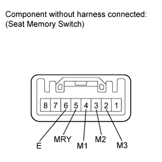 |
Remove the seat memory switch (Click here).
Measure the resistance according to the value(s) in the table below.
- Standard Resistance:
Tester Connection
Switch Condition
Specified Condition
4 (M1) - 6 (E)
Seat memory switch 1 pressed
Below 1 Ω
3 (M2) - 6 (E)
Seat memory switch 2 pressed
Below 1 Ω
2 (M3) - 6 (E)
Seat memory switch 3 pressed
Below 1 Ω
5 (MRY) - 6 (E)
Seat memory SET switch pressed
Below 1 Ω
|
|
||||
| OK | |
|
| 6. CHECK HARNESS AND CONNECTOR (OUTER MIRROR CONTROL ECU - SEAT MEMORY SWITCH) |
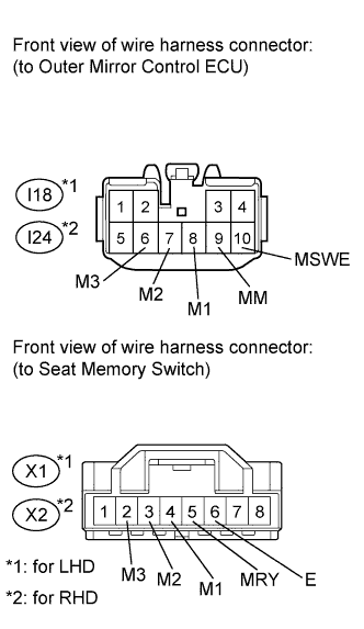 |
Disconnect the I18*1 or I24*2 ECU connector.
Disconnect the X1*1 or X2*2 switch connector.
- HINT:
- *1: for LHD
- *2: for RHD
Measure the resistance according to the value(s) in the table below.
- Standard Resistance:
for LHD Tester Connection
Condition
Specified Condition
I18-8 (M1) - X1-4 (M1)
Always
Below 1 Ω
I18-7 (M2) - X1-3 (M2)
Always
Below 1 Ω
I18-6 (M3) - X1-2 (M3)
Always
Below 1 Ω
I18-9 (MM) - X1-5 (MRY)
Always
Below 1 Ω
I18-10 (MSWE) - X1-6 (E)
Always
Below 1 Ω
I18-8 (M1) - Body ground
Always
10 kΩ or higher
I18-7 (M2) - Body ground
Always
10 kΩ or higher
I18-6 (M3) - Body ground
Always
10 kΩ or higher
I18-9 (MM) - Body ground
Always
10 kΩ or higher
I18-10 (MSWE) - Body ground
Always
10 kΩ or higher
for RHD Tester Connection
Condition
Specified Condition
I24-8 (M1) - X2-4 (M1)
Always
Below 1 Ω
I24-7 (M2) - X2-3 (M2)
Always
Below 1 Ω
I24-6 (M3) - X2-2 (M3)
Always
Below 1 Ω
I24-9 (MM) - X2-5 (MRY)
Always
Below 1 Ω
I24-10 (MSWE) - X2-6 (E)
Always
Below 1 Ω
I24-8 (M1) - Body ground
Always
10 kΩ or higher
I24-7 (M2) - Body ground
Always
10 kΩ or higher
I24-6 (M3) - Body ground
Always
10 kΩ or higher
I24-9 (MM) - Body ground
Always
10 kΩ or higher
I24-10 (MSWE) - Body ground
Always
10 kΩ or higher
|
|
||||
| OK | |
|
| 7. CHECK OUTER MIRROR CONTROL ECU (OPERATION) |
After replacing the outer mirror control ECU, check that the front power seat control functions operate normally using the front seat switches and seat memory switch.
- OK:
- Front power seat control functions operate normally.
|
|
||||
| OK | ||
|
||
| ||