REMOVAL
Removal / installation · Vehicles built from Jan 2012
| 1. REMOVE EXHAUST MANIFOLD ASSEMBLY |

| 2. REMOVE CAMSHAFT SUB-ASSEMBLY |
| 3. REMOVE NO. 1 VALVE ROCKER ARM SUB-ASSEMBLY |
Remove the 32 No. 1 valve rocker arms from the cylinder head.
- HINT:
- Arrange the removed parts in the correct order.
| 4. REMOVE VALVE LASH ADJUSTER ASSEMBLY |
Remove the 32 valve lash adjusters from the cylinder head.
- HINT:
- Arrange the removed parts in the correct order.
| 5. REMOVE VALVE STEM CAP |
Remove the 32 valve stem caps from the cylinder head.
- HINT:
- Arrange the removed parts in the correct order.
| 6. REMOVE CYLINDER HEAD SUB-ASSEMBLY LH |
Uniformly loosen and remove the 2 bolts in the sequence shown in the illustration.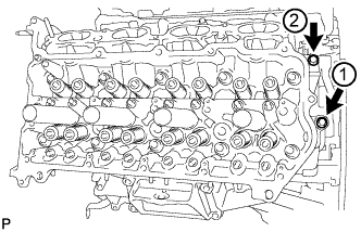

Using a 10 mm bi-hexagon wrench, uniformly loosen the 10 cylinder head bolts in the sequence shown in the illustration. Remove the 10 cylinder head bolts and plate washers.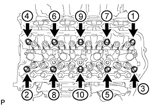
- NOTICE:
- Be careful not to drop washers into the cylinder head.
- Head warpage or cracking could result from removing bolts in an incorrect order.
- Be careful not to drop washers into the cylinder head.
- HINT:
- Be sure to arrange the removed parts for each installation position separately.
Remove the cylinder head LH.
| 7. REMOVE NO. 2 CYLINDER HEAD GASKET |
| 8. REMOVE CYLINDER HEAD SUB-ASSEMBLY |
Uniformly loosen and remove the 2 bolts in the sequence shown in the illustration.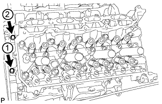
Using a 10 mm bi-hexagon wrench, uniformly loosen the 10 cylinder head bolts in the sequence shown in the illustration. Remove the 10 cylinder head bolts and plate washers.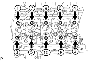
- NOTICE:
- Be careful not to drop washers into the cylinder head.
- Head warpage or cracking could result from removing bolts in an incorrect order.
- Be careful not to drop washers into the cylinder head.
- HINT:
- Be sure to arrange the removed parts for each installation position separately.
Remove the cylinder head.
| 9. REMOVE CYLINDER HEAD GASKET |
| 10. INSPECT CYLINDER HEAD SET BOLT |
Using a vernier caliper, measure the length of the cylinder head set bolt from the seat to the end.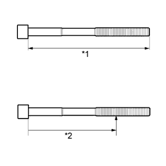
- Standard length:
- 141.3 to 142.7 mm (5.56 to 5.62 in.)
- Maximum length:
- 143.7 mm (5.66 in.)
If the length is more than the maximum, replace the cylinder head set bolt.Text in Illustration *1
Measurement Length
*2
Distance
Using a vernier caliper, measure the diameter of the elongated threads around the point indicated in the illustration.
- Distance:
Item
Specified Condition
Intake side bolt
103 mm (4.06 in.)
Exhaust side bolt
108 mm (4.25 in.)
- Standard diameter:
- 10.85 to 11.00 mm (0.427 to 0.433 in.)
- Minimum diameter:
- 10.60 mm (0.417 in.)
- HINT:
- If a visual check reveals no excessively thin areas, check the area of the bolt around the point indicated in the illustration and find the area that has the smallest diameter.
| 11. INSPECT CYLINDER HEAD SUB-ASSEMBLY |
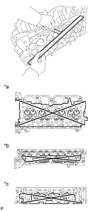 |
Using a precision straightedge and feeler gauge, measure the warpage of the contact surfaces of the cylinder block and manifold.
- Standard Warpage:
Item
Specified Condition
Cylinder block side
0.05 mm (0.00197 in.)
Intake manifold side
0.08 mm (0.00315 in.)
Exhaust manifold side
0.05 mm (0.00197 in.)
- Maximum warpage:
- 0.10 mm (0.00394 in.)
If the warpage is more than the maximum, replace the cylinder head sub-assembly.Text in Illustration *a
for Cylinder Block Side
*b
for Intake Manifold Side
*c
for Exhaust Manifold Side
Using a dye penetrant, check the intake ports, exhaust ports and cylinder head surface for cracks.
If cracked, replace the cylinder head sub-assembly.