Removal / installation · Vehicles built Sep 2011 – Dec 2011
Versions by build date: Sep 2011 – Dec 2011from Jan 2012
1.
INSTALL AIR FUEL RATIO SENSOR (for Bank 2 Sensor 1)
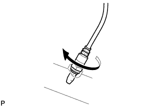
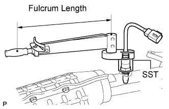
Temporarily install the sensor to the exhaust manifold by hand.
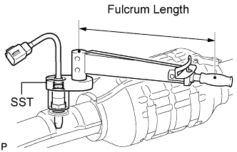
Using SST, tighten the sensor.
SST
09224-00010
Torque:
without SST:
44 N*m{
449 kgf*cm
, 32 ft.*lbf
}
with SST:
40 N*m{
408 kgf*cm
, 30 ft.*lbf
}
HINT:
Use a torque wrench with a fulcrum length of 30 cm (11.8 in.). If using a torque wrench with a length that is not 30 cm (11.8 in.), calculate the torque specification for the torque wrench and SST based on the "without SST" torque specification (Click here).
Make sure SST and the wrench are connected in a straight line.
2.
INSTALL EXHAUST MANIFOLD SUB-ASSEMBLY LH
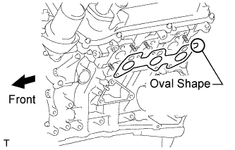
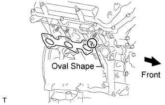
Set a new gasket to the cylinder head LH with the oval shape facing rearward.
NOTICE:
Be careful of the installation direction.
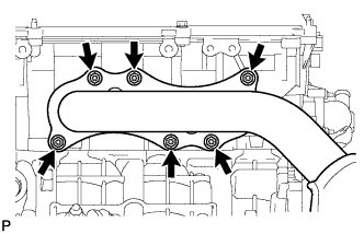
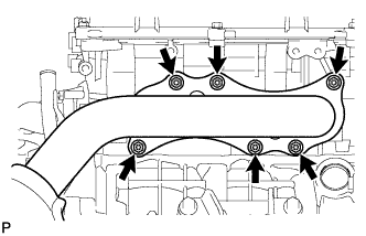
Install the exhaust manifold with 6 new nuts.
Torque:
30 N*m{
306 kgf*cm
, 22 ft.*lbf
}
Connect the air fuel ratio sensor connector.
3.
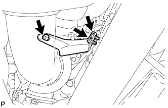
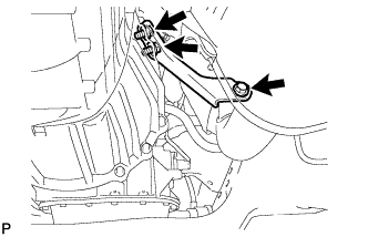
INSTALL NO. 2 MANIFOLD STAY
Install the No. 2 manifold stay with the 3 bolts.
Torque:
40 N*m{
408 kgf*cm
, 30 ft.*lbf
}
4.
INSTALL AIR FUEL RATIO SENSOR (for Bank 1 Sensor 1)
Temporarily install the sensor to the exhaust manifold by hand.
Using SST, tighten the sensor.
SST
09224-00010
Torque:
without SST:
44 N*m{
449 kgf*cm
, 32 ft.*lbf
}
with SST:
40 N*m{
408 kgf*cm
, 30 ft.*lbf
}
HINT:
Use a torque wrench with a fulcrum length of 30 cm (11.8 in.). If using a torque wrench with a length that is not 30 cm (11.8 in.), calculate the torque specification for the torque wrench and SST based on the "without SST" torque specification (Click here).
Make sure SST and the wrench are connected in a straight line.
5.
INSTALL EXHAUST MANIFOLD SUB-ASSEMBLY RH
Set a new gasket to the cylinder head RH with the oval shape facing forward.
NOTICE:
Be careful of the installation direction.
Install the exhaust manifold with 6 new nuts.
Torque:
30 N*m{
306 kgf*cm
, 22 ft.*lbf
}
Connect the air fuel ratio sensor connector.
6.
INSTALL NO. 1 MANIFOLD STAY
Install the No. 1 manifold stay with the 3 bolts.
Torque:
40 N*m{
408 kgf*cm
, 30 ft.*lbf
}
7.
INSTALL FRONT EXHAUST PIPE ASSEMBLY
Install 2 new gaskets to the front exhaust pipe.
Install the front exhaust pipe to the exhaust manifold RH with 2 new nuts.
Torque:
54 N*m{
554 kgf*cm
, 40 ft.*lbf
}
Install the 2 compression springs and 2 bolts to the center exhaust pipe.
Torque:
43 N*m{
438 kgf*cm
, 32 ft.*lbf
}
Connect the heated oxygen sensor connector.
8.
INSTALL FRONT NO. 2 EXHAUST PIPE ASSEMBLY
Install 2 new gaskets to the front No. 2 exhaust pipe.
Install the front No. 2 exhaust pipe to the exhaust manifold LH with 2 new nuts.
Torque:
54 N*m{
554 kgf*cm
, 40 ft.*lbf
}
Install the 2 bolts to the center exhaust pipe.
Torque:
48 N*m{
489 kgf*cm
, 35 ft.*lbf
}
Connect the heated oxygen sensor connector.
9.
INSPECT FOR EXHAUST GAS LEAK
If gas is leaking, tighten the areas necessary to stop the leak. Replace damaged parts as necessary.