INSTALLATION
Removal / installation · Vehicles built Sep 2011 – Dec 2011
Versions by build date: Sep 2011 – Dec 2011 from Jan 2012
| 1.
INSTALL FUEL SUPPLY PUMP |
 |
- NOTICE:
- Do not push the supply pump drive gear.
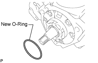
- Install a new O-ring to the supply pump.
Apply a light coat of engine oil to the O-ring.
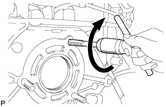
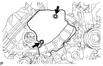
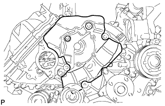
- Using an 8 mm x 1.25 pitch tap, remove the adhesive from the timing gear case side bolt hole.
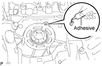
- Apply adhesive to 2 or more threads as shown in the illustration.
- Adhesive:
- Toyota Genuine Adhesive 1344, Three Bond 1344 or equivalent
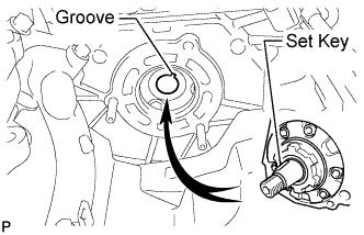
- Align the set key on the drive shaft with the groove of the supply pump drive gear.
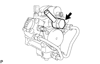
- NOTICE:
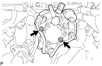
- Do not hold the supply pump by the parts indicated by the arrows in the illustration, as this may result in deformation, damage, and fuel leakage.
-
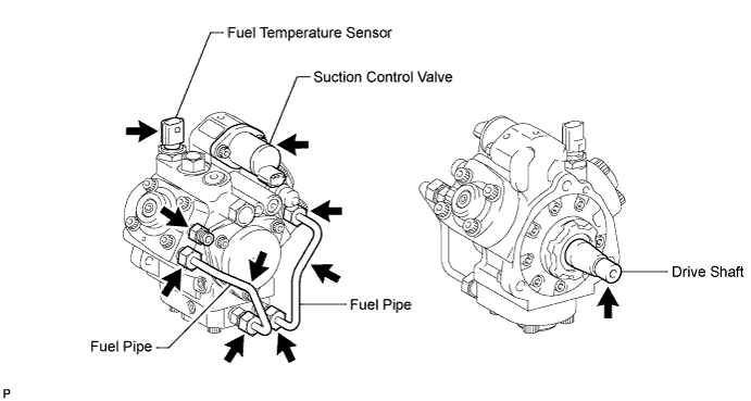

- Temporarily install the fuel supply pump with the 2 nuts.
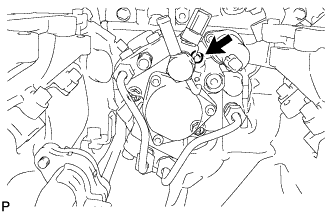
- Using a 6 mm hexagon wrench, install the bolt.
-
Torque:
- 21 N*m{
214 kgf*cm
, 15 ft.*lbf
}
Tighten the 2 nuts.
-
Torque:
- 21 N*m{
214 kgf*cm
, 15 ft.*lbf
}
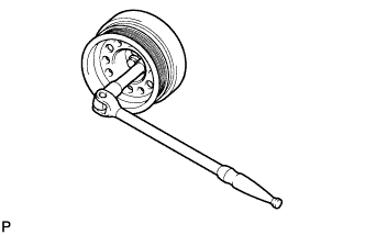
- Using a wrench, hold the crankshaft.
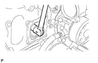
- Install the set nut.
-
Torque:
- 68 N*m{
693 kgf*cm
, 50 ft.*lbf
}
Turn the crankshaft 2 times, and check that there are no problems.
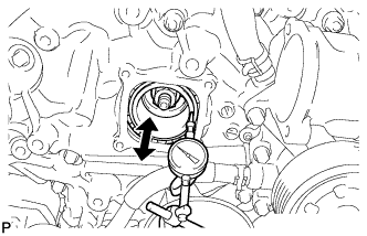
- Using a dial indicator, check the thrust clearance of the supply pump drive shaft while moving the pump drive shaft gear back and forth.
- Standard thrust clearance:
- 0.05 to 0.30 mm (0.00197 to 0.0118 in.)
If the clearance is not within the specified range, disassemble and reassemble the supply pump and pump drive shaft gear. Then repeat the step above.
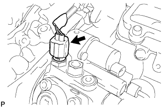
- Connect the fuel temperature sensor connector.
| 2.
INSTALL NO. 1 FUEL PIPE |
|
- Install 2 new gaskets and the No. 1 fuel pipe with the union bolt.
-
Torque:
- 17 N*m{
175 kgf*cm
, 13 ft.*lbf
}
| 3.
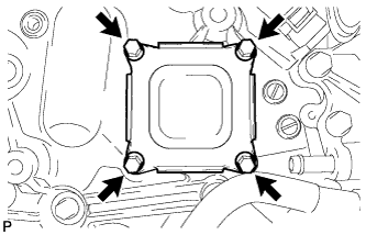
INSTALL TIMING CHAIN COVER PLATE |
|
- Install a new gasket and the cover plate with the 4 bolts.
-
Torque:
- 9.1 N*m{
93 kgf*cm
, 81 in.*lbf
}
| 4.
INSTALL TIMING GEAR COVER INSULATOR (w/ Intercooler)
|
|
- w/o Viscous Heater:
Install the timing gear cover insulator with the 2 bolts.
-
Torque:
- 21 N*m{
214 kgf*cm
, 15 ft.*lbf
}
- w/ Viscous Heater:
Install the timing gear cover insulator.
| 5.
INSTALL FUEL COOLER ASSEMBLY |
|
Install the fuel cooler assembly (Click here).
| 6.
INSTALL THERMOSTAT |
|
Install the thermostat (Click here).
| 7.
CONNECT CABLE TO NEGATIVE BATTERY TERMINAL |
|
- NOTICE:
- When disconnecting the cable, some systems need to be initialized after the cable is reconnected (Click here).
Connect the cables to the negative (-) main battery and sub-battery terminals.
| 8.
FUEL SUPPLY PUMP INITIALIZATION |
|
Initialize the fuel supply pump (Click here).