INSPECTION
Inspection · Vehicles built from Sep 2011
| INSPECT WINCH WIRE |

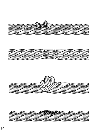  |
Inspect the wire for the following damage: 1) areas where several strands are severed; 2) areas where the diameter is less than 7.5 mm (0.295 in.); 3) kinks; 4) corrosion; and 5) fraying.
If the wire is damaged, replace it with a new one.
| INSPECT WINCH MOTOR ARMATURE SUB-ASSEMBLY |
Inspect the commutator for a shot circuit.
Measure the resistance according to the value(s) in the table below.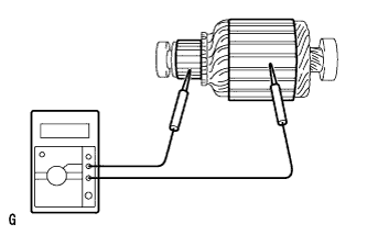
- Standard Resistance:
Tester Connection
Condition
Specified Condition
Commutator - Armature core
Always
10 kΩ or higher
Using a dial indicator, measure the circle runout of the commutator.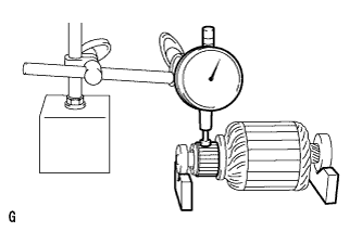
- Standard runout:
- 0.05 mm (0.0020 in.) or less
- Maximum runout:
- 0.2 mm (0.008 in.)
Using a vernier caliper, measure the diameter of the commutator.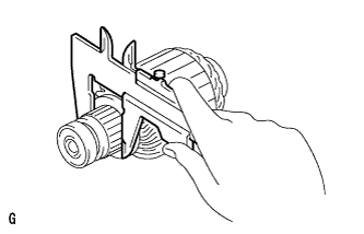
- Standard diameter:
- 43 mm (1.69 in.)
- Minimum diameter:
- 41 mm (1.61 in.)
Check that the undercut depth is clean and free of foreign particles. Then smooth off the edge and measure the undercut depth.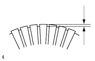
- Standard undercut depth:
- 0.5 to 0.8 mm (0.020 to 0.031 in.)
- Minimum undercut depth:
- 0.2 mm (0.008 in.)
| INSPECT WINCH MOTOR YOKE SUB-ASSEMBLY |
Inspect for an open circuit.
Measure the resistance according to the value(s) in the table below.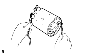
- Standard Resistance:
Tester Connection
Condition
Specified Condition
Lead wire - Field coil brush lead
Always
10 kΩ or higher
Inspect the shunt coil for an open circuit.
Measure the resistance according to the value(s) in the table below.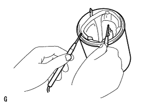
- Standard Resistance:
Tester Connection
Condition
Specified Condition
Field coil brush lead - Field frame
Always
Below 1 Ω
| INSPECT WINCH MOTOR BRUSH |
Using a vernier caliper, measure the length of the brush.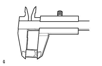
- Standard length:
- 22 mm (0.87 in.)
- Minimum length:
- 15 mm (0.59 in.)
| INSPECT WINCH MOTOR BRUSH SPRING |
Using a pull scale, measure the installed load of the brush spring.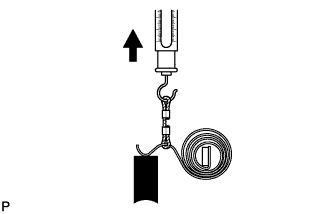
- Standard installed load:
- 16 to 20 N (1.6 to 2.0 kgf 3.6 to 4.4 lbf)
- HINT:
- Take the pull scale reading at the very instant the brush spring separates from the brush.
| INSPECT WINCH MOTOR BRUSH HOLDER ASSEMBLY |
Inspect for an open circuit.
Measure the resistance according to the value(s) in the table below.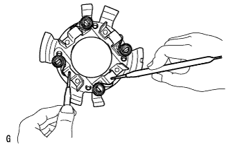
- Standard Resistance:
Tester Connection
Condition
Specified Condition
Positive (+) brush holder - Negative (-) brush holder
Always
Below 1 Ω
| INSPECT NO. 1 WINCH MOTOR ARMATURE BEARING |
Turn each bearing by hand while applying inward force.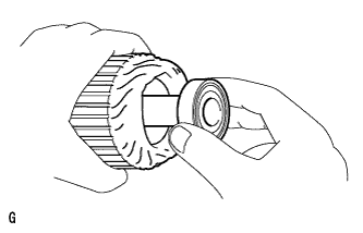
If the bearing sticks or resists, replace it.