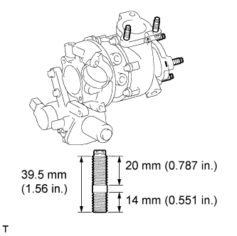
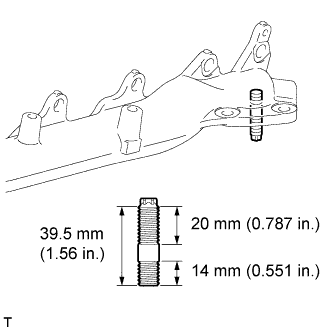
REMOVAL
Removal / installation · Vehicles built Sep 2011 – Dec 2011
Versions by build date: Sep 2011 – Dec 2011 from Jan 2012
| 1.
DISCONNECT CABLE FROM NEGATIVE BATTERY TERMINAL |
 |
- CAUTION:
- Wait at least 90 seconds after disconnecting the cable from the negative (-) battery terminal to disable the SRS system.
- NOTICE:
- When disconnecting the cable, some systems need to be initialized after the cable is reconnected (Click here).
Disconnect the cables from the negative (-) main battery and sub-battery terminals.
| 2.
REMOVE ENGINE ASSEMBLY |
|
Remove the engine assembly from the vehicle (Click here).
| 3.
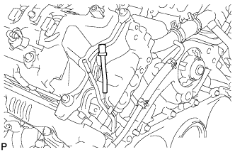
REMOVE NO. 1 ENGINE OIL LEVEL DIPSTICK GUIDE (for Bank 1) |
|
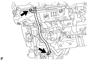
- Remove the 2 bolts and No. 1 engine oil level dipstick guide.
Remove the O-ring from the No. 1 engine oil level dipstick.
| 4.
REMOVE NO. 1 INTAKE AIR CONNECTOR PIPE (for Bank 1) |
|
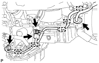
- Disconnect the 4 connectors.
Using a clip remover, detach the 5 wire harness clamps.
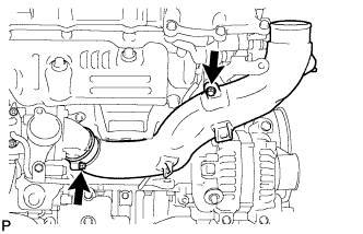
- Loosen the hose clamp, and remove the bolt and No. 1 intake air connector pipe.
| 5.
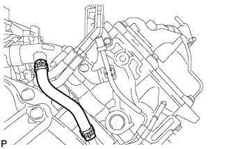
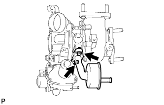
DISCONNECT NO. 2 VENTILATION HOSE (for Bank 1) |
|
| 6.
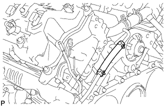
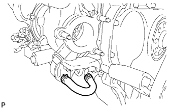
DISCONNECT NO. 2 TURBO WATER HOSE (for Bank 1) |
|
| 7.
DISCONNECT BREATHER PLUG RH (for Bank 1) |
|
| 8.
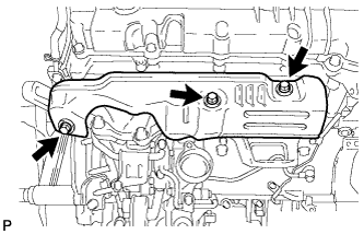
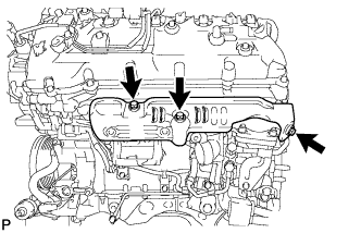
REMOVE NO. 1 EXHAUST MANIFOLD HEAT INSULATOR (for Bank 1) |
|
- Remove the 3 bolts and No. 1 exhaust manifold heat insulator.
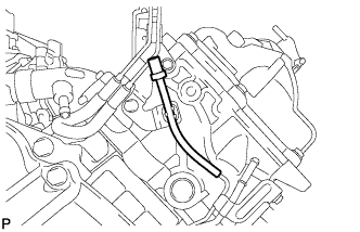
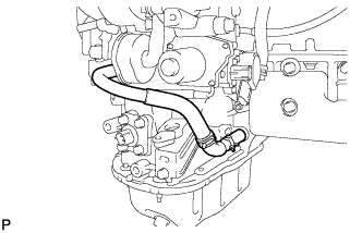
| 9.
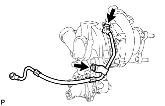
DISCONNECT NO. 1 OUTLET TURBO OIL HOSE (for Bank 1) |
|
| 10.
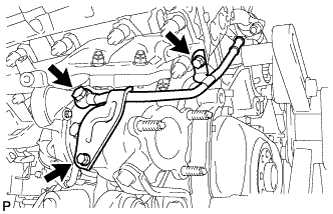
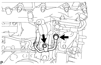
REMOVE NO. 1 TURBO WATER PIPE SUB-ASSEMBLY (for Bank 1) |
|
- Disconnect the water hose.
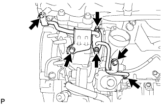
Remove the 3 bolts, 2 nuts, No. 1 turbo water pipe and gasket.
| 11.
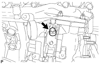
REMOVE NO. 1 TURBOCHARGER STAY (for Bank 1) |
|
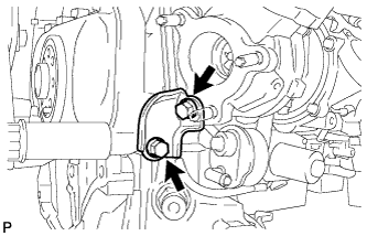
- Remove the 2 bolts and No. 1 turbocharger stay.
| 12.
REMOVE NO. 1 VENTILATION TUBE SUB-ASSEMBLY (for Bank 1) |
|
- Disconnect the vacuum hose.
Remove the union bolt, bolt, No. 1 ventilation tube and gasket.
| 13.
REMOVE NO. 1 TURBOCHARGER SUB-ASSEMBLY WITH EXHAUST MANIFOLD RH (for Bank 1) |
|
- Remove the union bolt and gasket, and disconnect the No. 1 inlet turbo oil pipe from the cylinder block.
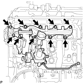
- Remove the 10 nuts, 10 collars and No. 1 turbocharger with exhaust manifold RH.
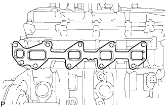
- Remove the gasket.
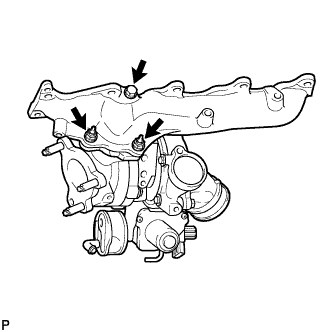
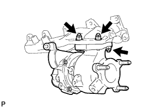
- Remove the 2 nuts and bolt, and separate the No. 1 turbocharger and exhaust manifold RH.
Remove the gasket from the No. 1 turbocharger.
| 14.
REMOVE NO. 1 INLET COMPRESSOR ELBOW (for Bank 1) |
|
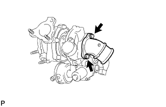
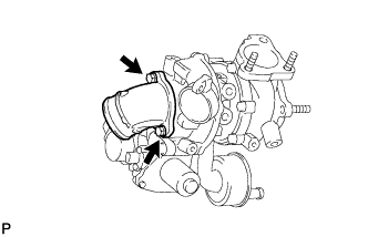
- Remove the 2 bolts, No. 1 inlet compressor elbow and gasket.
| 15.
REMOVE NO. 1 TURBO OIL PIPE (for Bank 1) |
|
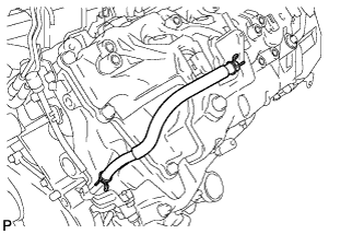
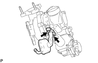
- Remove the 2 bolts, No. 1 turbo oil pipe and gasket.
| 16.
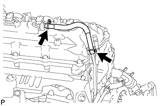
REMOVE NO. 1 INLET TURBO OIL PIPE SUB-ASSEMBLY (for Bank 1) |
|
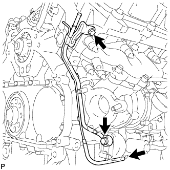
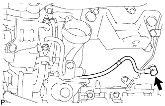
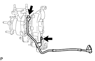
- Remove the union bolt, bolt, No. 1 inlet turbo oil pipe and gasket.
| 17.
DISCONNECT NO. 3 VENTILATION HOSE (for Bank 2) |
|
| 18.
DISCONNECT BREATHER PLUG LH (for Bank 2) |
|
| 19.
DISCONNECT NO. 2 TURBO WATER HOSE (for Bank 2) |
|
| 20.
REMOVE NO. 2 EXHAUST MANIFOLD HEAT INSULATOR (for Bank 2) |
|
- Remove the 3 bolts and No. 2 exhaust manifold heat insulator.
| 21.
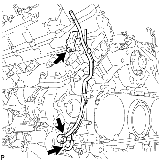
REMOVE NO. 3 TURBO WATER PIPE SUB-ASSEMBLY (for Bank 2) |
|
- Remove the 2 bolts, union bolt, No. 3 turbo water pipe and gasket.
| 22.
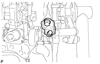
REMOVE FRONT WATER BY-PASS JOINT (for Bank 2) |
|
- Remove the front water by-pass joint and gasket.
| 23.
REMOVE NO. 2 TURBO WATER PIPE SUB-ASSEMBLY (for Bank 2) |
|
- Disconnect the water hose.
Remove the union bolt, bolt, No. 2 turbo water pipe and gasket.
| 24.
DISCONNECT NO. 2 OUTLET TURBO OIL HOSE (for Bank 2) |
|
| 25.
REMOVE NO. 2 TURBOCHARGER STAY (for Bank 2) |
|
- Remove the 2 bolts and No. 2 turbocharger stay.
| 26.
REMOVE NO. 2 VENTILATION TUBE SUB-ASSEMBLY (for Bank 2) |
|
- Disconnect the No. 2 vacuum transmitting hose.
Remove the union bolt, bolt, No. 2 ventilation tube and gasket.
| 27.
REMOVE NO. 2 TURBOCHARGER SUB-ASSEMBLY WITH EXHAUST MANIFOLD LH (for Bank 2) |
|
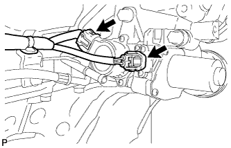
- Disconnect the 2 connectors from the turbocharger.
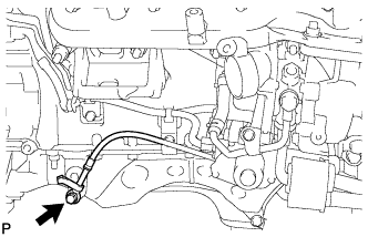
- Remove the union bolt and gasket, and disconnect the No. 2 inlet turbo oil pipe.
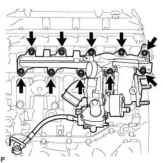
- Remove the 10 nuts, 10 collars and No. 2 turbocharger with exhaust manifold LH.
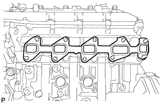
- Remove the gasket.
- Remove the 3 nuts, and separate the No. 2 turbocharger and exhaust manifold LH.
Remove the gasket from the turbocharger.
| 28.
REMOVE NO. 2 INLET COMPRESSOR ELBOW (for Bank 2) |
|
- Remove the 2 bolts, No. 2 inlet compressor elbow and gasket.
| 29.
REMOVE NO. 2 TURBO OIL PIPE (for Bank 2) |
|
- Remove the 2 bolts, No. 2 turbo oil pipe and gasket.
| 30.
REMOVE NO. 2 INLET TURBO OIL PIPE SUB-ASSEMBLY (for Bank 2) |
|
- Remove the union bolt, bolt, No. 2 inlet turbo oil pipe and gasket.
| 31.
REPLACE STUD BOLT |
|
- HINT:
- If a stud bolt is deformed or the threads are damaged, replace it.
for No. 1 Turbocharger:
Using an E10 "TORX" wrench, replace the stud bolts labeled A and B shown in the illustration below.
-
Torque:
- 20 N*m{
204 kgf*cm
, 15 ft.*lbf
}
for No. 1 Turbocharger:
Replace the stud bolts labeled C shown in the illustration below.
-
Torque:
- 6.0 N*m{
61 kgf*cm
, 53 in.*lbf
}
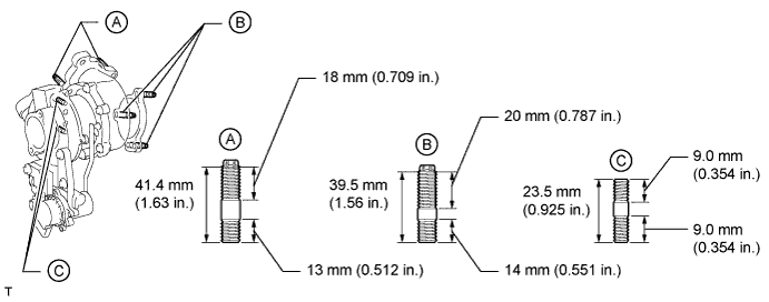

- for No. 2 Turbocharger:
Using an E10 "TORX" wrench, replace the stud bolt.
-
Torque:
- 20 N*m{
204 kgf*cm
, 15 ft.*lbf
}
- for Exhaust Manifold RH:
Using an E10 "TORX" wrench, replace the stud bolt.
-
Torque:
- 20 N*m{
204 kgf*cm
, 15 ft.*lbf
}