TERMINALS OF ECU
System information · Vehicles built Sep 2011 – Dec 2011
Versions by build date: Sep 2011 – Dec 2011 from Jan 2012
| CHECK REAR TELEVISION CAMERA ASSEMBLY |


Disconnect the S5 camera connector.
Measure the voltage and resistance according to the value(s) in the table below.
If the result is not as specified, there may be a malfunction on the wire harness side.Terminal No. (Symbol)
Wiring Color
Terminal Description
Condition
Specified Condition
S5-3 (CGND) - Body ground
BR - Body ground
Ground
Always
Below 1 Ω
S5-4 (CB+) - S5-3 (CGND)
B - BR
Power source
Engine switch on (IG), shift lever moved to R
5.8 to 6.5 V
Reconnect the S5 camera connector.
Measure the waveform according to the value(s) in the table below.
If the result is not as specified, the camera may have a malfunction.Terminal No. (Symbol)
Wiring Color
Terminal Description
Condition
Specified Condition
S5-2 (CV+) - S5-1 (CV-)
R - W
Display signal
Engine switch on (IG), shift lever moved to R
Waveform 1
Using an oscilloscope, check waveform 1.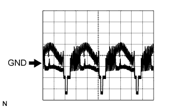
Waveform 1 (Reference) Item
Content
Terminal No. (Symbol)
S5-2 (CV+) - S5-1 (CV-)
Tool Setting
0.2 V/DIV., 0.2 μs/DIV.
Condition
Engine switch on (IG), shift lever moved to R
| CHECK MULTI-DISPLAY |
- for HDD navigation system (Click here)
- for DVD navigation system (Click here)