REMOVAL
Removal / installation · Vehicles built from Jan 2012
| 1. PRECAUTION |

- NOTICE:
- After turning the ignition switch off, waiting time may be required before disconnecting the cable from the battery terminal. Therefore, make sure to read the disconnecting the cable from the battery terminal notice before proceeding with work (Click here).
| 2. DISCONNECT CABLE FROM NEGATIVE BATTERY TERMINAL |
- NOTICE:
- When disconnecting the cable, some systems need to be initialized after the cable is reconnected (Click here).
| 3. REMOVE TONNEAU COVER ASSEMBLY (w/ Tonneau Cover) |
Remove the tonneau cover.
| 4. REMOVE REAR NO. 2 SEAT ASSEMBLY RH (w/ Rear No. 2 Seat) |
- HINT:
- Use the same procedure described for the LH side.
| 5. REMOVE REAR STEP COVER |
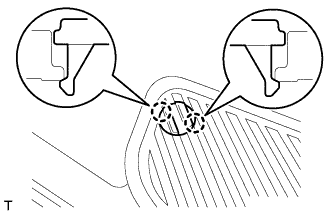  |
- HINT:
- Use the same procedure to remove the step cover on the other side.
Detach the 2 claws and remove the step cover.
| 6. REMOVE REAR DOOR SCUFF PLATE RH |
- HINT:
- Use the same procedures described for the LH side.
| 7. REMOVE REAR FLOOR MAT REAR SUPPORT PLATE |
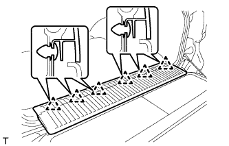 |
Detach the 6 clips and remove the support plate.
| 8. REMOVE REAR SEAT COVER CAP RH (w/ Rear No. 2 Seat) |
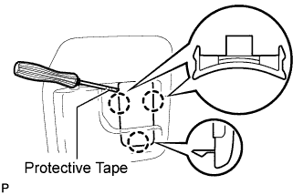 |
- HINT:
- Use the same procedure to remove the rear seat cover cap on the other side.
Using a screwdriver, detach the 3 claws and remove the rear seat cover cap.
- HINT:
- Tape the screwdriver tip before use.
| 9. REMOVE FRONT QUARTER TRIM PANEL ASSEMBLY RH |
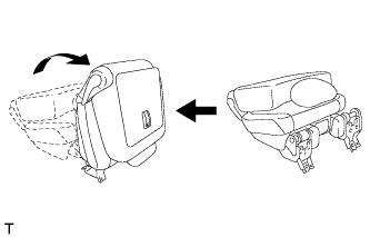 |
- HINT:
- When removing the front quarter trim panel, operate the reclining adjuster release handle and move the No. 1 rear seat to the position shown in the illustration.
Detach the 3 claws and remove the cover.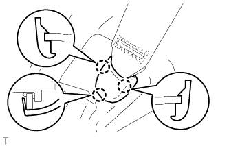
Remove the bolt and rear No. 1 seat belt anchor.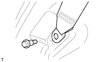
w/ Rear No. 2 Seat, except Face to Face Seat Type: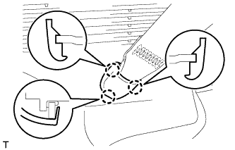
Detach the 3 claws and remove the cover.
Remove the bolt and rear No. 2 seat belt anchor.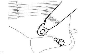
w/ Rear No. 2 Seat, except Face to Face Seat Type:
Remove the clip and bolt.
Detach the 16 clips and 2 claws.
w/o Rear Air Conditioning System:
Disconnect the rear seat lock control lever cable and then remove the quarter trim panel.w/ Rear Air Conditioning System:
Disconnect the thermistor connector and rear seat lock control lever cable, and then remove the quarter trim panel.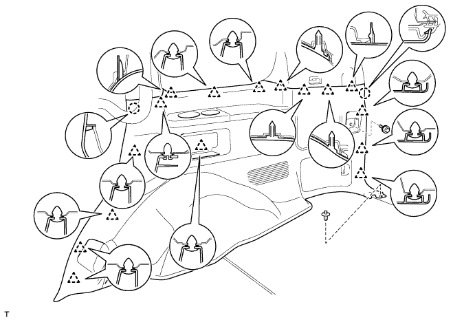
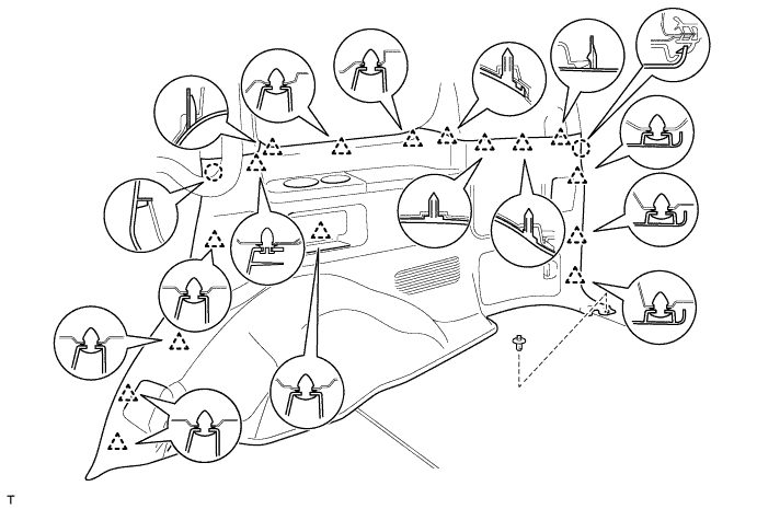
w/o Rear No. 2 Seat or w/ Rear No. 2 Seat, for Face to Face Seat Type:
Remove the clip.
Detach the 16 clips and 2 claws, and remove the quarter trim panel.
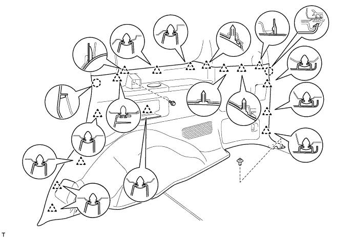
w/ Tonneau Cover:
Remove the screw and clip.
Detach the 16 clips and 2 claws, and remove the quarter trim panel.
| 10. REMOVE CENTER BACK DOOR GARNISH |
Detach the 5 clips and 4 claws, and remove the center back door garnish.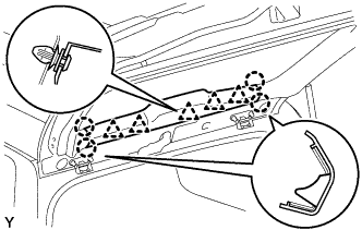
| 11. REMOVE BACK DOOR SIDE GARNISH RH |
w/o Power Back Door:
- HINT:
- Use the same procedure described for the LH side.
w/ Power Back Door: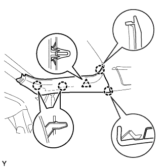
Detach the clip and 4 claws, and remove the back door side garnish RH.
| 12. REMOVE BACK DOOR SERVICE HOLE COVER RH |
Move the back door to a half-open position so that the hole in the center of the back door service hole cover RH is aligned lengthwise with the power back door rod.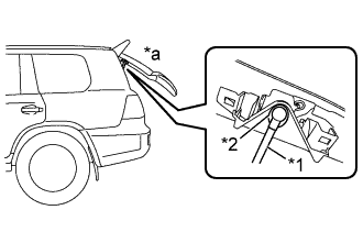
Text in Illustration *1
Power Back Door Rod
*2
Hole of Back Door Service Hole Cover RH
*a
Back Door is Half-open
Detach the 2 clips and separate the back door service hole cover RH, passing the power back door rod through the hole of the back door service hole cover RH.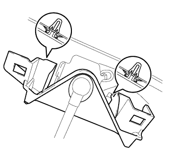
- NOTICE:
- If the back door is in a fully-open position, the power back door rod will interfere with the hole of the back door service hole cover RH, so do not perform this operation with the back door in a fully open position.
- HINT:
- If any of the clips have remained on the back door, remove the clips from the back door and install them to the back door service hole cover RH.
Remove the ball joint bolt, power back door rod and back door stay plate.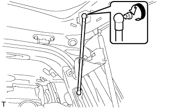
Remove the back door service hole cover RH from the power back door rod.
| 13. REMOVE REAR UPPER PILLAR GARNISH RH |
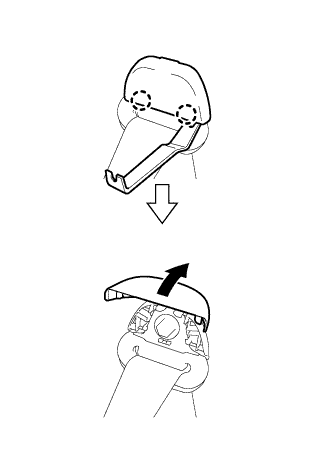 |
Using a moulding remover, detach the 2 claws and open the seat belt shoulder anchor cover.
Remove the bolt and seat belt shoulder anchor.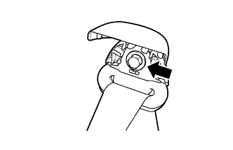
w/o Power Back Door: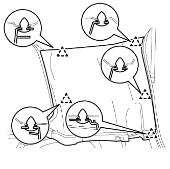
Detach the 5 clips and remove the rear upper pillar garnish.
w/ Power Back Door: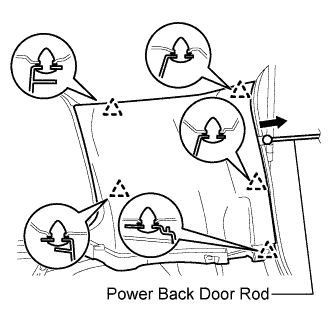
Detach the 5 clips.
Pass the power back door rod through the rear upper pillar garnish, and remove the rear upper pillar garnish.
| 14. REMOVE POWER BACK DOOR UNIT ASSEMBLY |
Disconnect the connector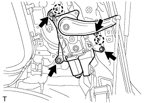
Remove the 4 bolts.
Detach the 2 claws and remove the power back door unit assembly.