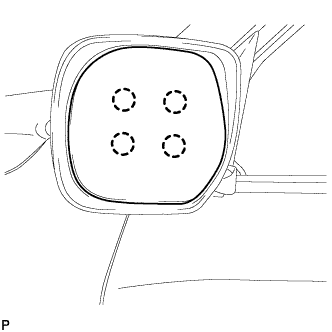
REASSEMBLY
Removal / installation · Vehicles built from Jan 2012
Versions by build date: Sep 2011 – Dec 2011 from Jan 2012
- HINT:
- Use the same procedure for the RH and LH sides.
- The procedure listed below is for the LH side.
- Use the same procedure for the RH and LH sides.
| 1. INSTALL SIDE TELEVISION CAMERA ASSEMBLY (w/ Side Monitor System) |

Install the side television camera with the 3 screws.
Connect the connector.
Install the body.
Attach the 2 guides and body.
- NOTICE:
- Be careful not to break the guide.
Install the body cover.
Install the body with the 5 screws.
Connect the connector.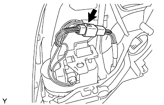

Attach the connector to the wire clip.
Install the base
Attach the guide.
Using "TORX" socket wrench T25, install the base with 3 new screws.
- NOTICE:
- When installing the base, check that the wire harness is not caught between the base and housing. Failure to do so may cause a short circuit.
Install the lower mirror cover.
Attach the 4 claws and install a new lower mirror cover.
Install the gasket.
Attach the 9 guides and install the gasket.
Align the marking on the wire harness with the marking on the end of the wire harness insertion hole of the gasket as shown in the illustration, and wrap them with new vinyl tape starting from the gasket marking.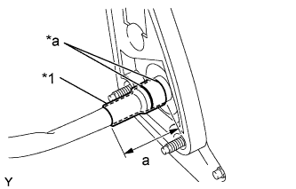
Text in Illustration *1
New Vinyl Tape
*a
Marking
- Standard:
Area
Specified Condition
a
50.0 mm (1.97 in.)
- NOTICE:
- If the vinyl tape is wrinkled, water may run down the wire harness and enter the vehicle. Make sure to wind the vinyl tape properly.
Wrap new vinyl tape as shown in the illustration.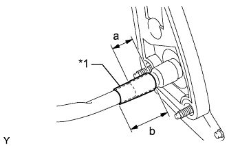
Text in Illustration *1
New Vinyl Tape
- Standard:
Area
Specified Condition
a
30.0 mm (1.18 in.)
b
50.0 mm (1.97 in.)
| 2. INSTALL SIDE TURN SIGNAL LIGHT ASSEMBLY LH |
Connect the connector.
Install the light with the 3 screws.
| 3. INSTALL OUTER MIRROR COVER |
Install the outer mirror cover.
Insert the rib on the outer edge of the cover into the groove of the mirror body.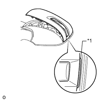
- NOTICE:
- Do not scratch the turn light.
Text in Illustration *1
Rib
While making sure that the rib of the cover fits properly into the groove of the mirror body, squeeze the inner end of the cover and the mirror body together to attach the inner claws.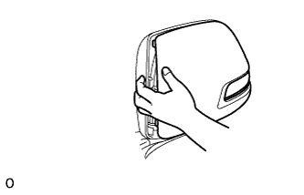
Push on the cover at the locations of the 8 claws to confirm that the claws are attached properly.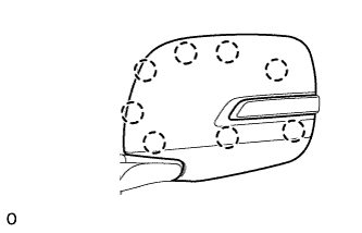
Check that there is no gap between the cover and mirror body.
- HINT:
- If there is a gap between the cover and body, noise will occur during driving.
| 4. INSTALL OUTER MIRROR LH |
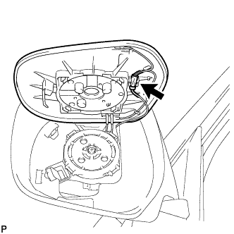 |
w/ EC Mirror:
Connect the connector.
w/ Mirror Heater: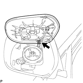
Connect the 2 connectors.
Attach the 4 claws to install the outer mirror LH.