Cooling Box Magnetic Valve Circuit
Circuit diagnosis · Vehicles built from Sep 2011
DESCRIPTION
The cooler expansion valve (cooler magnetic valve) is controlled by the air conditioning amplifier assembly (for cool box).WIRING DIAGRAM
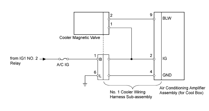

INSPECTION PROCEDURE
| 1. INSPECT FUSE (A/C IG) |

Remove the A/C IG fuse from the cowl side junction block LH.
Measure the resistance according to the value(s) in the table below.
- Standard Resistance:
Tester Connection
Condition
Specified Condition
A/C IG fuse
Always
Below 1 Ω
|
|
||||

| OK | |
 |
| 2. CHECK HARNESS AND CONNECTOR (NO. 1 COOLER WIRING HARNESS - BATTERY) |
Disconnect the No. 1 cooler wiring harness sub-assembly connector.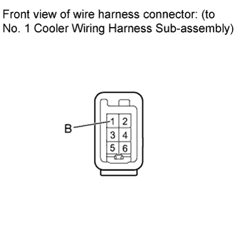
Measure the voltage according to the value(s) in the table below.
- Standard Voltage:
Tester Connection
Switch Condition
Specified Condition
1 (B) - Body ground
Engine switch off
Below 1 V
Engine switch on (IG)
11 to 14 V
|
|
||||
| OK | |
|
| 3. CHECK HARNESS AND CONNECTOR (NO. 1 COOLER WIRING HARNESS - BODY GROUND) |
Disconnect the No. 1 cooler wiring harness sub-assembly connector.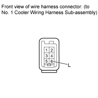
Measure the resistance according to the value(s) in the table below.
- Standard Resistance:
Tester Connection
Condition
Specified Condition
6 (L) - Body ground
Always
Below 1 Ω
|
|
||||
| OK | |
|
| 4. CHECK NO. 1 COOLER WIRING HARNESS SUB-ASSEMBLY (OPERATION) |
Replace the No. 1 cooler wiring harness sub-assembly with a normal one and check that the condition returns to normal.
- OK:
- Same problem does not occur.
|
|
||||

| OK | ||
 |
||
| ||
| 5. CHECK COOLER MAGNETIC VALVE (OPERATION) |
Replace the cooler magnetic valve (Click here).
- HINT:
- Since the cooler magnetic valve cannot be inspected while it is removed from the vehicle, replace the cooler magnetic valve with a normal one and check that the condition returns to normal.
- OK:
- Same problem does not occur.
|
|
||||
| OK | ||
|
||
| ||