INSTALLATION
Removal / installation · Vehicles built from Jan 2012
| 1. INSTALL DIFFERENTIAL PRESSURE SENSOR ASSEMBLY |

for Bank 1:
Install the differential pressure sensor with the bolt.
- Torque:
- 5.0 N*m{ 51 kgf*cm , 44 in.*lbf }
Install the sensor bracket with the bolt.
- Torque:
- 31 N*m{ 316 kgf*cm , 23 ft.*lbf }
Install the No. 1 air hose and No. 2 air hose to the differential pressure sensor with 2 new clips.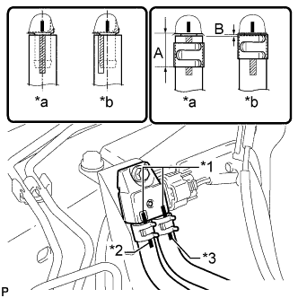

- NOTICE:
- Connect the air hoses so that the paint marks of the air hoses are as shown in the illustration.
- Make sure the end of the clip is 14.3 mm (0.563 in.) or less from the end of the exhaust pipe air hose when installing the clip as shown by A in the illustration.
- Make sure the clip does not protrude beyond the end of the hose as shown by B in the illustration.
- Connect the air hoses so that the paint marks of the air hoses are as shown in the illustration.
Text in Illustration *1
Marking
*2
Orange Paint Mark
*3
White Paint Mark
*a
CORRECT
*b
INCORRECT
Connect the differential pressure sensor connector.
for Bank 2:
Install the differential pressure sensor with the bolt.
- Torque:
- 14 N*m{ 137 kgf*cm , 10 ft.*lbf }
Install the sensor bracket with the bolt.
- Torque:
- 31 N*m{ 316 kgf*cm , 23 ft.*lbf }
Install the No. 3 air hose and No. 4 air hose to the differential pressure sensor with 2 new clips.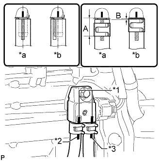
- NOTICE:
- Connect the air hoses so that the paint marks of the air hoses are as shown in the illustration.
- Make sure the end of the clip is 14.3 mm (0.563 in.) or less from the end of the exhaust pipe air hose when installing the clip as shown by A in the illustration.
- Make sure the clip does not protrude beyond the end of the hose as shown in by B the illustration.
- Connect the air hoses so that the paint marks of the air hoses are as shown in the illustration.
Text in Illustration *1
Marking
*2
Yellow Paint Mark
*3
Green Paint Mark
*a
CORRECT
*b
INCORRECT
Connect the differential pressure sensor connector and attach the clamp.
Attach the 4 wire harness clamps.
Install the front propeller shaft (Click here).