1VD-FTV FUEL FUEL SUB TANK INSTALLATION
PROCEDURE

 77213E
1.INSTALL FUEL TANK TO FILLER PIPE HOSE
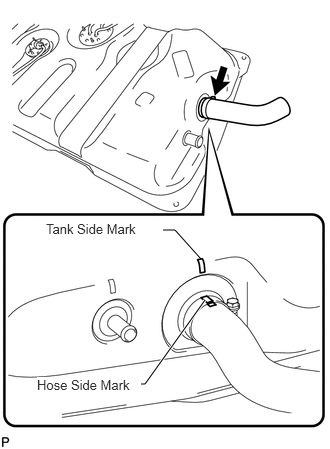
Install the hose to the fuel sub tank as shown in the illustration.
- HINT:
- ·
Align the fuel sub tank side mark with the hose side mark when installing the hose.
·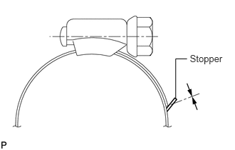 2.777,0.77 3.316,0.952 0.539,0.183 10 Stopper 2.736,0.858 2.57,0.858 2.57,0.858 2.57,1.44 false
Tighten the hose clamp until the end of the hose clamp contacts the stopper as shown in the illustration.
77419
2.INSTALL NO. 3 FUEL HOSE
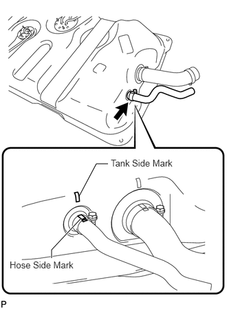
Install the fuel hose to the fuel sub tank as shown in the illustration.
- HINT:
- ·
Align the fuel sub tank side mark with the hose side mark when installing the hose.
·
2.777,0.77 3.316,0.952 0.539,0.183 10 Stopper 2.736,0.858 2.57,0.858 2.57,0.858 2.57,1.44 false
Tighten the hose clamp until the end of the hose clamp contacts the stopper as shown in the illustration.
77269A
3.INSTALL FUEL TANK BREATHER HOSE
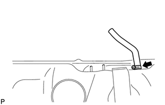
Install the breather hose to the fuel sub tank.
77017
4.INSTALL FUEL AND EVAPORATION VENT TUBE SUB-ASSEMBLY
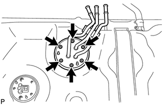
Install a new gasket to the fuel and evaporation vent tube.
Install the fuel and evaporation vent tube with the 6 bolts.
- Torque:
- 3.5 N*m (36 kgf*cm, 31 in.*lbf)
77018E
5.INSTALL FUEL TANK EVAPORATION VENT TUBE SUB-ASSEMBLY
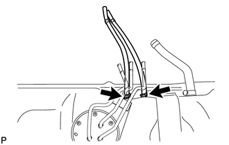
Install the 2 fuel tank evaporation vent tubes.
77259E
6.INSTALL FUEL HOSE
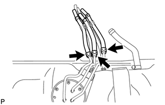
Install the 3 fuel hoses.
83320B
7.INSTALL FUEL SENDER GAUGE ASSEMBLY
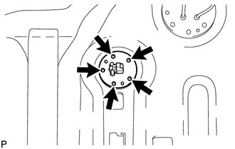
Install a new gasket to the sender gauge.
- NOTICE:
-
Be careful not to bend the arm of the fuel sender gauge.
Install the sender gauge with the 5 screws.
- Torque:
- 1.5 N*m (15 kgf*cm, 13 in.*lbf)
82163
8.INSTALL FLOOR NO. 3 WIRE
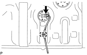
Attach the wire harness clamp to the fuel sub tank.
Connect the sender gauge connector.
77100Z
9.INSTALL FUEL SUB TANK SUB-ASSEMBLY
Set the fuel sub tank on a transmission jack and raise the fuel sub tank.
- NOTICE:
-
Do not allow the fuel sub tank to contact the vehicle, especially the differential.
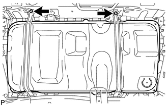
Connect the 2 fuel tank bands with the 2 bolts.
- Torque:
- 40 N*m (408 kgf*cm, 30 ft.*lbf)
Connect the floor No. 3 wire connector.
Attach the 3 wire harness clamps.
77213B
10.CONNECT FUEL TANK TO FILLER PIPE HOSE
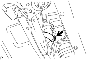
Connect the hose to the filler pipe.
11.CONNECT NO. 3 FUEL HOSE
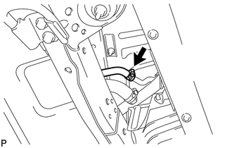
Connect the fuel hose to the filler pipe.
12.CONNECT FUEL TANK BREATHER HOSE
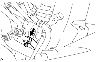
Connect the breather hose to the filler pipe.
77001U
13.CONNECT FUEL HOSE
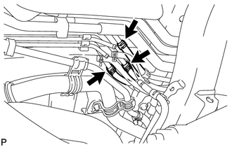
Connect the 3 fuel hoses.
14.CONNECT FUEL TANK EVAPORATION VENT TUBE
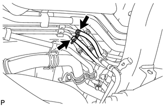
Connect the 2 fuel evaporation vent tubes.
77310A
15.INSTALL FUEL TANK CAP ASSEMBLY
51933A
16.INSTALL NO. 1 SPARE WHEEL STOPPER
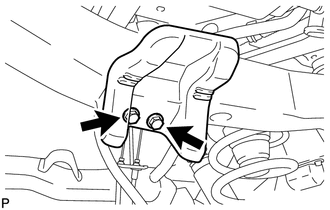
Install the spare wheel stopper with the 2 bolts.
- Torque:
- 32 N*m (326 kgf*cm, 24 ft.*lbf)
51949B
17.INSTALL SPARE WHEEL CARRIER CROSSMEMBER AND SPARE WHEEL CARRIER BRACKET
Install the spare wheel carrier crossmember and 2 brackets to the vehicle body with the 6 bolts labeled C.
- Torque:
- for bolt C : 20 N*m (204 kgf*cm, 15 ft.*lbf)
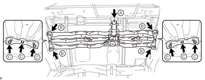
Temporarily install the bolt labeled A, and then tighten the bolt labeled A and bolts labeled B.
- Torque:
- for bolt A : 29 N*m (296 kgf*cm, 21 ft.*lbf)
- for bolt B : 20 N*m (204 kgf*cm, 15 ft.*lbf)
17430
18.INSTALL TAILPIPE ASSEMBLY
19.BLEED AIR FROM FUEL SYSTEM
20.CONNECT CABLE TO NEGATIVE BATTERY TERMINAL
- NOTICE:
-
When disconnecting the cable, some systems need to be initialized after the cable is reconnected (See page General>INTRODUCTION>REPAIR INSTRUCTION>INITIALIZATION).
Connect the cables to the negative (-) main battery and sub-battery terminals.
21.INSPECT FOR FUEL LEAK
22.INSPECT FOR EXHAUST GAS LEAK
23.INSTALL SPARE TIRE