RM2660E
_51
Engine / Hybrid System
_052784
1GR-FE EMISSION CONTROL
_0255130
AIR SWITCHING VALVE(for Bank 1)
A
1GR-FE EMISSION CONTROL AIR SWITCHING VALVE(for Bank 1) INSTALLATION
PROCEDURE

 25701B
1.INSTALL NO. 1 EMISSION CONTROL VALVE SET
a.
Install the No. 1 emission control valve set with the 3 nuts.
- Torque:
- 21 N*m (214 kgf*cm, 15 ft.*lbf)
b.
0.688,0.188 0.792,0.188
0.792,0.188 1.031,0.729
true
1.625,1.052 1.552,1.052
1.552,1.052 1.281,0.76
true
2.906,0.135 3.083,0.313
0.177,0.177
10
false
*a
1.885,0.688 2.063,0.865
0.177,0.177
10
false
*b
0.5,0.115 0.677,0.292
0.177,0.177
10
false
*1
1.646,0.969 1.823,1.146
0.177,0.177
10
false
*2
2.042,0.896 2.302,1.042
0.26,0.146
10
false
60°
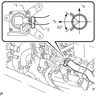
Align the paint mark with the rib and connect the No. 1 air hose.
| *1 | Rib |
| *2 | Paint Mark |
| *a | RH Side |
| *b | Top |
- HINT:
-
Make sure the direction of the hose clamp is as shown in the illustration.
c.
Connect the No. 1 emission control valve set connector.
17361
2.INSTALL AIR TUBE
a.
2.733,0.939 2.899,1.095
0.166,0.156
10
*1
2.997,0.756 3.163,0.912
0.166,0.156
10
*2
2.725,1.031 2.594,1.031
2.594,1.031 2.508,0.679
false
2.982,0.855 2.921,0.855
2.921,0.855 2.859,0.666
false
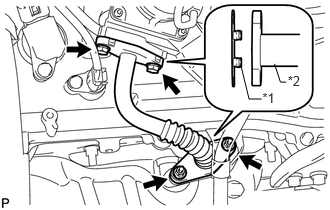
Install 2 new gaskets.
| *1 | Claw |
| *2 | Air Tube |
- NOTICE:
-
Make sure the gasket's claws are not caught between the No. 1 emission control valve set and air tube.
b.
Install the air tube with the 2 bolts and 2 nuts.
- Torque:
- 10 N*m (102 kgf*cm, 7 in.*lbf)
3.INSTALL AIR CLEANER CAP AND HOSE
11259
4.INSTALL V-BANK COVER