RM2660E
_52
Drivetrain
_052806
A750F AUTOMATIC TRANSMISSION / TRANSAXLE
_0255289
SHIFT LEVER
A
A750F AUTOMATIC TRANSMISSION / TRANSAXLE SHIFT LEVER INSTALLATION
PROCEDURE

 1.INSTALL TRANSMISSION FLOOR SHIFT ASSEMBLY
0.75,1.104 0.865,1.26
0.115,0.156
10
false
3
2.677,0.229 2.792,0.385
0.115,0.156
10
false
4
2.802,1.042 2.917,1.198
0.115,0.156
10
false
2
0.865,0.094 0.979,0.25
0.115,0.156
10
false
1
a.
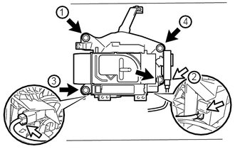
Install the transmission floor shift assembly with the 4 bolts. Tighten the bolts in the order shown in the illustration.
- Torque:
- 14 N*m (143 kgf*cm, 10 ft.*lbf)

|
Bolt |

|
Connector |
b.
Connect the 3 connectors.
33702B
2.CONNECT FLOOR SHIFT GEAR SHIFTING ROD SUB-ASSEMBLY
1.042,0.188 1.177,0.365
0.135,0.177
10
false
P
1.5,0.344 1.635,0.521
0.135,0.177
10
false
R
1.76,0.031 1.896,0.208
0.135,0.177
10
false
N
a.
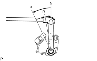
Turn the control shaft lever RH of the park/neutral position switch counterclockwise until it stops, and then turn it clockwise 2 notches to set it to the N position.
b.
Move the shift lever to N.
c.
1.917,0.604 1.344,0.281
1.344,0.281 1.24,0.281
true
1.01,0.188 1.198,0.375
0.188,0.188
10
false
*a
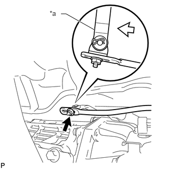
Temporarily install the floor shift gear shifting rod sub-assembly to the transmission floor shift assembly with the nut.
d.
Tighten the nut while lightly pushing the lever rearward.
- Torque:
- 13 N*m (130 kgf*cm, 9 ft.*lbf)
| *a | Lever |
|
|
Nut |
|
|
Push |
3.INSTALL FRONT CONSOLE BOX (w/o Cool Box)
4.INSTALL FRONT CONSOLE BOX (w/ Cool Box)