DRIVE SHAFT / PROPELLER SHAFT PROPELLER SHAFT ASSEMBLY REASSEMBLY
PROCEDURE

 04371H
1.INSTALL REAR PROPELLER SHAFT UNIVERSAL JOINT SPIDER ASSEMBLY
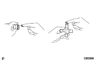
Apply MP grease to a new spider and new bearings.
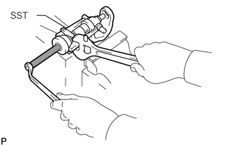
Fit the spider into the flange yoke.
Using SST, install the bearings to the spider.
- SST
- 09332-25010
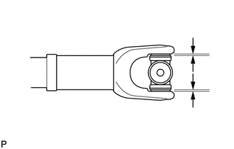
Using SST, adjust both bearings so that the snap ring grooves are at maximum and equal in width.
- SST
- 09332-25010
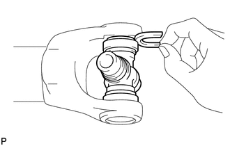
Install 2 new snap rings of equal thickness which will allow 0 mm (0 in.) of axial play.
- HINT:
-
Do not reuse the snap rings.
- Standard Snap Ring Thickness (for 3UR-FE):
Part No. Mark
ColorSpecified Condition 90520-29024 - 1.985 to 2.015 mm
(0.0782 to 0.0793 in.)90520-29025 Light Brown 2.015 to 2.045 mm
(0.0794 to 0.0805 in.)90520-29026 Blue 2.045 to 2.075 mm
(0.0806 to 0.0816 in.)90520-29027 - 2.075 to 2.105 mm
(0.0817 to 0.0828 in.)90520-29039 1 1.98 to 2.00 mm
(0.0780 to 0.0787 in.)90520-29040 2 2.00 to 2.02 mm
(0.0788 to 0.0795 in.)90520-29041 3 2.02 to 2.04 mm
(0.0796 to 0.0803 in.)90520-29042 4 2.04 to 2.06 mm
(0.0804 to 0.0811 in.)90520-29043 5 2.06 to 2.08 mm
(0.0812 to 0.0818 in.)90520-29044 6 2.08 to 2.10 mm
(0.0819 to 0.0826 in.)90520-29045 7 2.10 to 2.12 mm
(0.0827 to 0.0834 in.)90520-29046 8 2.12 to 2.14 mm
(0.0835 to 0.0842 in.)90520-29047 
2.14 to 2.16 mm
(0.0843 to 0.0850 in.)90520-29048 10 2.16 to 218 mm
(0.0851 to 0.0858 in.)
- Standard Snap Ring Thickness (except 3UR-FE):
Part No. Mark
ColorSpecified Condition 90520-25054 J 2.18 to 2.20 mm
(0.0859 to 0.0866 in.)90520-25055 K 2.20 to 2.22 mm
(0.0867 to 0.0874 in.)90520-25056 F 2.22 to 2.24 mm
(0.0875 to 0.0881 in.)90520-25057 G 2.24 to 2.26 mm
(0.0882 to 0.0899 in.)90520-25058 H 2.26 to 2.28 mm
(0.0890 to 0.0897 in.)90520-25039 1 2.28 to 2.30 mm
(0.0898 to 0.0905 in.)90520-25040 2 2.30 to 2.32 mm
(0.0906 to 0.0913 in.)90520-25041 - 2.32 to 2.34 mm
(0.0914 to 0.0921 in.)90520-25042 Brown 2.34 to 2.36 mm
(0.0922 to 0.0929 in.)90520-25043 Blue 2.36 to 2.38 mm
(0.0930 to 0.0937 in.)90520-25044 6 2.38 to 2.40 mm
(0.0938 to 0.0944 in.)90520-25045 7 2.40 to 2.42 mm
(0.0945 to 0.0952 in.)90520-25046 8 2.42 to 2.44 mm
(0.0953 to 0.0960 in.)90520-25047
2.44 to 2.46 mm
(0.0961 to 0.0968 in.)90520-25048 10 2.46 to 2.48 mm
(0.0969 to 0.0976 in.)90520-25049 A 2.48 to 2.50 mm
(0.0977 to 0.0984 in.)90520-25050 B 2.50 to 2.52 mm
(0.0985 to 0.0992 in.)90520-25051 C 2.52 to 2.54 mm
(0.0993 to 0.0999 in.)90520-25052 D 2.54 to 2.56 mm
(0.1000 to 0.1007 in.)90520-25053 E 2.56 to 2.58 mm
(0.1008 to 0.1015 in.)
Using a hammer, tap the yoke until there is no clearance between the bearing outer race and snap ring.
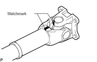
Align the matchmarks on the propeller shaft and flange yoke or flange yoke and sleeve yoke.
Install the flange yoke to the sleeve yoke or propeller shaft.
- HINT:
-
Install 2 new spider bearings and snap rings on the flange yoke side using the procedure described above.
2.APPLY MP GREASE
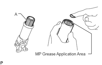
Apply MP grease to the propeller shaft (the edge of the spline) as shown in the illustration.
- Amount (Reference):
Spline A Amount Silver 44 to 54 g (1.56 to 1.90 oz.) Black 9 to 17 g (0.32 to 0.59 oz.)
- HINT:
-
The amount of grease differs depending on the color of the spline portion of the sleeve yoke.
Align the matchmarks and install the sleeve yoke to the propeller shaft.
- NOTICE:
- ·
Do not scratch the spline portion.
·Make sure that there is no foreign matter.
37140
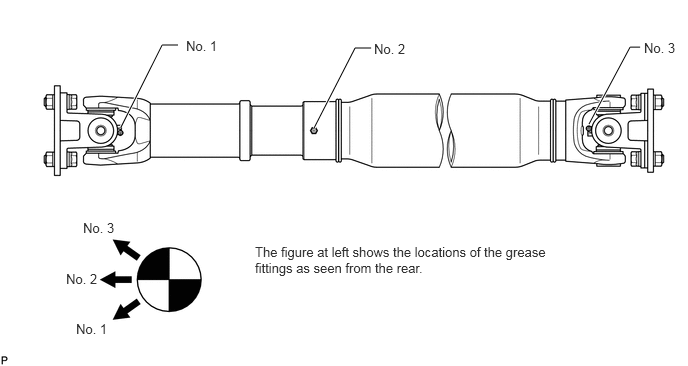
3.INSPECT PROPELLER SHAFT GREASE FITTING DIRECTION
- HINT:
-
When replacing a spider bearing, be sure that the grease fitting hole is facing the direction shown in the illustration.
4.INSPECT SPIDER BEARING