SUSPENSION CONTROL DAMPING FORCE CONTROL ACTUATOR(for Front Side) INSTALLATION
CAUTION / NOTICE / HINT
- HINT:
- ·
Use the same procedures for the RH side and LH side.
·The procedures listed below are for the LH side.
·A bolt without a torque specification is shown in the standard bolt chart (See page General>SPECIFICATIONS>STANDARD BOLT>SPECIFIED TORQUE FOR STANDARD BOLTS).
PROCEDURE

 49020
1.INSTALL FRONT SUSPENSION CONTROL VALVE ASSEMBLY LH
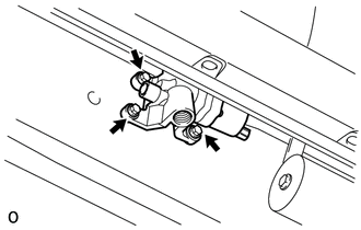
Install the control valve to the vehicle with the 3 bolts.
- Torque:
- 31 N*m (316 kgf*cm, 23 ft.*lbf)
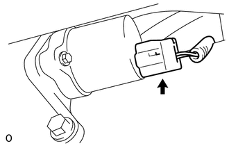
Connect the control valve connector.
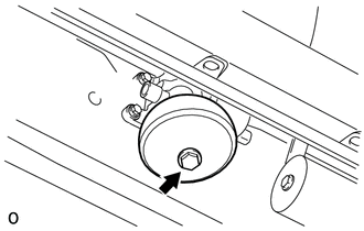
Apply a small amount of suspension fluid to a new O-ring and new back-up ring and install then to the accumulator.
Install the accumulator to the control valve.
- Torque:
- 150 N*m (1530 kgf*cm, 111 ft.*lbf)
48020B
2.INSTALL FRONT SHOCK ABSORBER CONTROL VALVE ASSEMBLY LH
Install the bleeder plug and bleeder plug cap to the control accumulator.
- Torque:
- 8.3 N*m (85 kgf*cm, 73 in.*lbf)
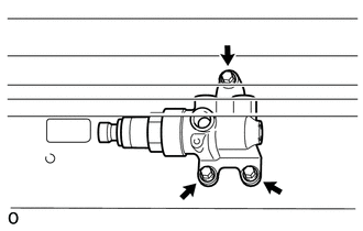
Install the control valve to the vehicle with the 3 bolts.
- Torque:
- 31 N*m (316 kgf*cm, 23 ft.*lbf)
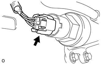
Connect the connector.
49040A
3.INSTALL FRONT NO. 2 SUSPENSION CONTROL ACCUMULATOR ASSEMBLY LH
Apply a small amount of suspension fluid to a new O-ring and install it to the accumulator.
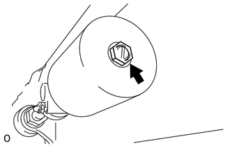
Install the accumulator to the shock absorber control valve.
- Torque:
- 57 N*m (581 kgf*cm, 42 ft.*lbf)
49162B
4.CONNECT NO. 2 SUSPENSION CONTROL PRESSURE HOSE
Install a new gasket to the No. 2 suspension control pressure hose, then connect the pressure hose to the control valve with the union bolt.
- Torque:
- 50 N*m (510 kgf*cm, 37 ft.*lbf)
48992
5.INSTALL NO. 2 HEIGHT CONTROL TUBE LH
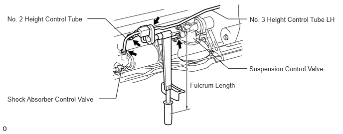
Using a union nut wrench, connect the No. 2 control tube to the No. 3 height control tube, shock absorber control valve and control valve.
- Torque:
- without union nut wrench : 44 N*m (450 kgf*cm, 33 ft.*lbf)
- with union nut wrench : 40 N*m (408 kgf*cm, 30 ft.*lbf)
- HINT:
- ·
Use a torque wrench with a fulcrum length of 300 mm (11.8 in.).
·The torque value for use with a union nut wrench is effective when the union nut wrench is parallel to the torque wrench.
Install the No. 2 control tube with the bolt.
- Torque:
- 31 N*m (316 kgf*cm, 23 ft.*lbf)
49140
6.INSTALL FRONT NO. 1 SUSPENSION CONTROL ACCUMULATOR ASSEMBLY LH
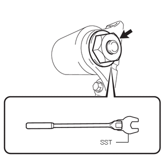
When installing a new front No. 1 suspension control accumulator:
Using a SST, remove the nut, washer and front No. 1 suspension control accumulator from the bracket.
- SST
- 09612-24014 (09617-22030)
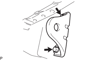
Install the front No. 1 suspension control accumulator bracket to the frame with the 2 bolts.
- Torque:
- 31 N*m (316 kgf*cm, 23 ft.*lbf)
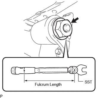
Using a SST, install the front No. 1 suspension control accumulator with the washer and nut.
- SST
- 09612-24014 (09617-22030)
- Torque:
- without SST:
190 N*m (1937 kgf*cm, 140 ft.*lbf)
- with SST:
166 N*m (1696 kgf*cm, 123 ft.*lbf)
- HINT:
- ·
Use a torque wrench with a fulcrum length of 400 mm (15.7 in.).
·The torque value for use with a SST is effective when the SST is parallel to the torque wrench.
48991A
7.INSTALL NO. 1 HEIGHT CONTROL TUBE LH
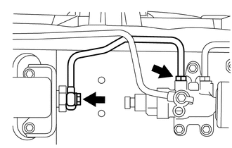
Install a new gasket to the No. 1 height control tube, then temporarily install No. 1 height control tube to the control valve and control accumulator with the union bolt and union nut.
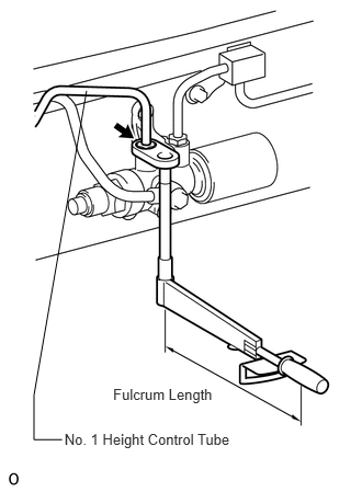
Using a union nut wrench, tighten the No. 1 height control tube.
- Torque:
- without union nut wrench : 44 N*m (450 kgf*cm, 33 ft.*lbf)
- with union nut wrench : 40 N*m (408 kgf*cm, 30 ft.*lbf)
- HINT:
- ·
Use a torque wrench with a fulcrum length of 300 mm (11.8 in.).
·The torque value for use with a union nut wrench is effective when the union nut wrench is parallel to the torque wrench.
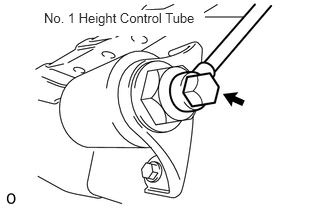
Tighten the union bolt.
- Torque:
- 43 N*m (438 kgf*cm, 32 ft.*lbf)
8.BLEED AIR FROM SUSPENSION FLUID
9.CHECK FLUID LEVEL IN RESERVOIR
10.INSPECT FOR SUSPENSION FLUID LEAK
489D0
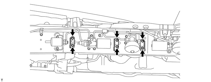
11.INSTALL HEIGHT CONTROL CYLINDER BRACKET ASSEMBLY
Install the 3 brackets with the 6 bolts.
- Torque:
- 31 N*m (316 kgf*cm, 23 ft.*lbf)
489B0
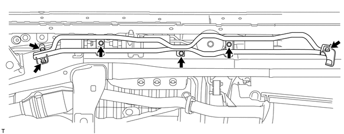
12.INSTALL HEIGHT CONTROL PROTECTOR PIPE
Install the protector pipe with the 6 bolts.
- Torque:
- 16 N*m (163 kgf*cm, 12 ft.*lbf)
13.INSTALL SIDE STEP ASSEMBLY LH