AUDIO / VIDEO AUDIO AND VISUAL SYSTEM(w/ Navigation System) Display Signal Circuit between Multi-display and Radio Receiver
DESCRIPTION
The display image signal from the multi-media module receiver assembly is sent to the multi-display assembly using a digital communication cable.
WIRING DIAGRAM
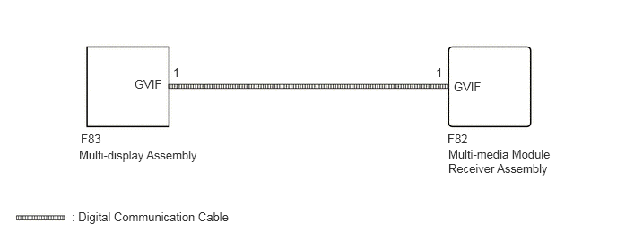
PROCEDURE
Check if the digital communication cable connectors between the multi-media module receiver assembly and the multi-display assembly have any connection problems (See page General>INTRODUCTION>HOW TO TROUBLESHOOT ECU CONTROLLED SYSTEMS>HOW TO PROCEED WITH TROUBLESHOOTING).
Check that the screen display is normal.
- OK:
Screen display is normal.
OK
(See pageGeneral>INTRODUCTION>HOW TO TROUBLESHOOT ECU CONTROLLED SYSTEMS>HOW TO PROCEED WITH TROUBLESHOOTING)
NG
Replace the multi-display assembly with a new or normally functioning one (See page Audio / Visual / Telematics>NAVIGATION / MULTI INFO DISPLAY>MULTI-DISPLAY (w/ Navigation System)>REMOVAL).
Check that the screen display is normal.
- OK:
Screen display is normal.
OK
NG