AUDIO / VIDEO AUDIO AND VISUAL SYSTEM(w/ Navigation System) B1579 Voice Recognition Microphone Disconnected
DESCRIPTION
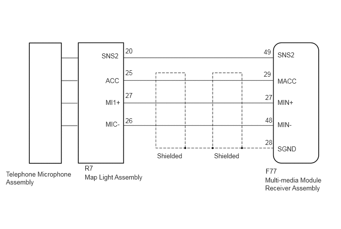
The multi-media module receiver assembly and map light assembly (telephone microphone assembly) are connected to each other using the microphone connection detection signal lines.
This DTC is stored when a microphone connection detection signal line is disconnected.
| DTC Code | DTC Detection Condition | Trouble Area |
|---|---|---|
| B1579 | Telephone microphone signal is lost. | ·
Multi-media module receiver assembly ·
Map light assembly ·
Telephone microphone assembly ·
Harness or connector |
WIRING DIAGRAM
PROCEDURE
Disconnect the F77 multi-media module receiver assembly connector.
Disconnect the R7 map light assembly connector.
Measure the resistance according to the value(s) in the table below.
- Standard Resistance:
Tester Connection Condition Specified Condition F77-49 (SNS2) - R7-20 (SNS2) Always Below 1 Ω F77-29 (MACC) - R7-25 (ACC) Always Below 1 Ω F77-27 (MIN+) - R7-27 (MI1+) Always Below 1 Ω F77-48 (MIN-) - R7-26 (MIC-) Always Below 1 Ω F77-49 (SNS2) - Body ground Always 10 kΩ or higher F77-29 (MACC) - Body ground Always 10 kΩ or higher F77-27 (MIN+) - Body ground Always 10 kΩ or higher F77-48 (MIN-) - Body ground Always 10 kΩ or higher F77-28 (SGND) - Body ground Always 10 kΩ or higher
OK
NG
Reconnect the multi-media module receiver assembly connector.
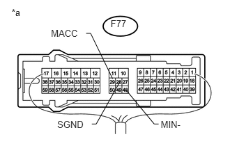
Measure the resistance according to the value(s) in the table below.
- Standard Resistance:
Tester Connection Condition Specified Condition F77-28 (SGND) - Body ground Always Below 1 Ω F77-48 (MIN-) - Body ground Always Below 1 Ω
Measure the voltage according to the value(s) in the table below.
- Standard Voltage:
Tester Connection Switch Condition Specified Condition F77-29 (MACC) - Body ground Engine switch on (ACC) 4 to 6 V
| *a | Component with harness connected
(Multi-media Module Receiver Assembly) |
OK
NG
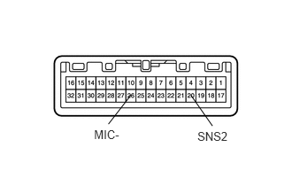
Remove the map light assembly (See page Audio / Visual / Telematics>AUDIO / VIDEO>MICROPHONE AMPLIFIER>REMOVAL).
Measure the resistance according to the value(s) in the table below.
- Standard Resistance:
Tester Connection Condition Specified Condition 26 (MIC-) - 20 (SNS2) Always Below 1 Ω
| *a | Component without harness connected
(Map Light Assembly) |
OK
NG
Reconnect the multi-media module receiver assembly connector.
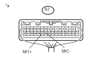
Reconnect the map light assembly connector.
Turn the engine switch on (ACC).
Connect an oscilloscope to terminals R7-27 (MI1+) and R7-26 (MIC-) of the map light assembly connector.
Check the waveform of the telephone microphone assembly using the oscilloscope.
| *a | Component with harness connected
(Map Light Assembly) |
| Result | Proceed to |
|---|---|
| A waveform synchronized with the voice input to the map light assembly is not output. | A |
| A waveform synchronized with the voice input to the map light assembly is output. | B |
A
B
Replace the telephone microphone assembly with a new or normally functioning one (See page Audio / Visual / Telematics>AUDIO / VIDEO>MICROPHONE AMPLIFIER>REMOVAL).
Check if the same DTC is output again.
| Result | Proceed to |
|---|---|
| No DTCs are output. | A |
| DTCs are output. | B |
A
B