Home › Audio / Visual / Telematics › AUDIO / VIDEO › AUDIO AND VISUAL SYSTEM (w/ Multi-display) › from 2015.08
RM2660E _56 Audio / Visual / Telematics _052828 AUDIO / VIDEO _0255488 AUDIO AND VISUAL SYSTEM(w/ Multi-display) C

AUDIO / VIDEO  AUDIO AND VISUAL SYSTEM(w/ Multi-display)  B157D  DAB Tuner Antenna Disconnected  


DESCRIPTION

This DTC is stored when a malfunction occurs in the digital audio broadcasting antenna assembly which is connected to the multi-media module receiver assembly.

DTC Code DTC Detection Condition Trouble Area
B157D The No. 2 amplifier antenna assembly is not connected
·

Antenna cord sub-assembly

·

No. 2 antenna cord sub-assembly

·

No. 4 antenna cord sub-assembly

·

Quarter window glass (Window glass antenna wire)

·

Multi-media module receiver assembly


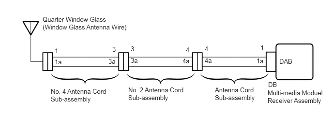
WIRING DIAGRAM

B386849E08
5.76,1.917 7,2.51 1.24,0.594 10 false Multi-media Moduel Receiver Assembly 5.771,1.74 6.115,1.948 0.344,0.208 10 false DB 5.604,0.948 5.729,1.156 0.125,0.208 10 false 1 5.521,1.229 5.719,1.438 0.198,0.208 10 false 1a 4.406,0.969 4.531,1.177 0.125,0.208 10 false 4 4.406,1.219 4.604,1.427 0.198,0.208 10 false 4a 4,0.99 4.125,1.198 0.125,0.208 10 false 4 3.927,1.229 4.125,1.438 0.198,0.208 10 false 4a 2.813,0.969 2.938,1.177 0.125,0.208 10 false 3 2.813,1.219 3.01,1.427 0.198,0.208 10 false 3a 2.417,0.979 2.542,1.188 0.125,0.208 10 false 3 2.333,1.24 2.531,1.448 0.198,0.208 10 false 3a 1.177,1.01 1.344,1.219 0.167,0.208 10 false 1 1.177,1.25 1.375,1.458 0.198,0.208 10 false 1a 6.01,1.24 6.438,1.51 0.427,0.271 10 false DAB 4.625,1.854 5.573,2.188 0.948,0.333 10 false Antenna Cord Sub-assembly 2.76,1.854 4.083,2.354 1.323,0.5 10 false No. 2 Antenna Cord Sub-assembly 1.094,1.885 2.396,2.385 1.302,0.5 10 false No. 4 Antenna Cord Sub-assembly 0.917,0.333 2.844,0.677 1.927,0.344 10 false Quarter Window Glass (Window Glass Antenna Wire)

CAUTION / NOTICE / HINT

NOTICE:

Check that the antenna cable is properly installed and does not have any sharp bends, pinching or loose connections.


PROCEDURE

1.CHECK CONNECTION OF DAB RADIO ANTENNA CABLE
a.

Check if the DAB radio antenna cable is securely connected to the multi-media module receiver assembly.

OK:

DAB radio antenna cable is securely connected.


OK

2.CHECK QUARTER WINDOW ASSEMBLY (WINDOW GLASS ANTENNA WIRE)

NG

SECURELY CONNECT DAB RADIO ANTENNA CABLE

2.CHECK QUARTER WINDOW ASSEMBLY (WINDOW GLASS ANTENNA WIRE)
a.

Inspect the quarter window glass (window glass antenna wire) (See page Audio / Visual / Telematics>AUDIO / VIDEO>WINDOW GLASS ANTENNA WIRE>REPAIR).


OK

3.CHECK ANTENNA CORD SUB-ASSEMBLY

NG

3.CHECK ANTENNA CORD SUB-ASSEMBLY
a.
U166554E02
2.031,2.802 2.406,3.104 2.406,3.104 2.635,3.104 false 1.844,1.188 2.198,1.448 2.198,1.448 2.49,1.448 false 1.688,1.063 1.146,0.438 1.146,0.438 0.854,0.438 false 0.135,0.094 0.406,0.313 0.271,0.219 10 false *a 2.552,1.375 2.823,1.594 0.271,0.219 10 false 1a 0.479,0.354 0.802,0.542 0.323,0.188 10 false DAB 0.76,0.844 0.979,1.021 0.219,0.177 10 false DB 0.167,1.667 0.438,1.885 0.271,0.219 10 false *b 2.76,3.01 3.031,3.229 0.271,0.219 10 false 4a

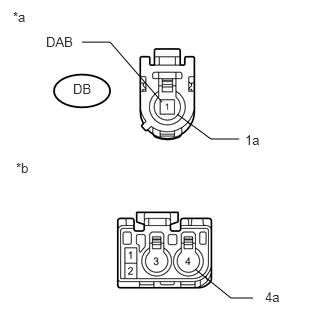
Remove the antenna connector from the multi-media module receiver assembly.


b.

Remove the antenna connector from the No. 2 antenna cord sub-assembly.


c.

Measure the resistance according to the value(s) in the table below.

Standard Resistance:
Tester Connection Condition Specified Condition
DB-1 (DAB) - 4 Always Below 1 Ω
DB-1a - 4a Always Below 1 Ω
DB-1 (DAB) or 4 - Body ground Always 10 kΩ or higher
DB-1a or 4a - Body ground Always 10 kΩ or higher


Text in Illustration
*a Front view of wire harness connector
(to Multi-media Module Receiver Assembly)
*b Front view of wire harness connector
(to No. 2 Antenna Cord Sub-assembly)


OK

4.CHECK NO. 2 ANTENNA CORD SUB-ASSEMBLY

NG

REPLACE ANTENNA CORD SUB-ASSEMBLY

4.CHECK NO. 2 ANTENNA CORD SUB-ASSEMBLY
a.
E329644E02
0.079,0.078 0.392,0.350 0.313,0.272 10 *a 0.626,0.423 0.939,0.695 0.313,0.272 10 4a 0.177,1.738 0.490,2.010 0.313,0.272 10 *b 1.349,1.082 1.024,0.533 1.024,0.533 0.861,0.533 false 2.695,2.502 2.887,2.700 0.192,0.198 10 3a 2.223,2.79 2.486,2.6 2.486,2.6 2.661,2.6 false

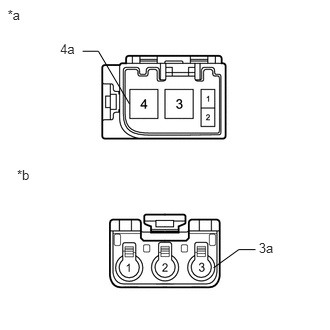
Remove the antenna connector from the antenna cord sub-assembly.


b.

Remove the antenna connector from the No. 4 antenna cord sub-assembly.


c.

Measure the resistance according to the value(s) in the table below.

Standard Resistance:
Tester Connection Condition Specified Condition
4 - 3 Always Below 1 Ω
4a - 3a Always Below 1 Ω
4 or 3 - Body ground Always 10 kΩ or higher
4a or 3a - Body ground Always 10 kΩ or higher


Text in Illustration
*a Front view of wire harness connector
(to Antenna Cord Sub-assembly)
*b Front view of wire harness connector
(to No. 4 Antenna Cord Sub-assembly)


OK

5.CHECK NO. 4 ANTENNA CORD SUB-ASSEMBLY

NG

REPLACE NO. 2 ANTENNA CORD SUB-ASSEMBLY

5.CHECK NO. 4 ANTENNA CORD SUB-ASSEMBLY
a.
E335248E01
0.077,0.064 0.335,0.285 0.258,0.221 10 *a 0.077,1.697 0.335,1.918 0.258,0.221 10 *b 0.524,0.454 0.735,0.625 0.211,0.171 10 3a 0.669,2.065 0.880,2.236 0.211,0.171 10 1a 0.764,0.54 0.931,0.54 0.931,0.54 1.417,0.935 false 0.919,2.163 1.086,2.163 1.086,2.163 1.565,2.554 false

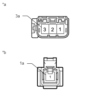
Remove the antenna connector from the No. 2 antenna cord sub-assembly.


b.

Remove the antenna connector from the quarter window glass.


c.

Measure the resistance according to the value(s) in the table below.

Standard Resistance:
Tester Connection Condition Specified Condition
3 - 1 Always Below 1 Ω
3a - 1a Always Below 1 Ω
3 or 1 - Body ground Always 10 kΩ or higher
3a or 1a - Body ground Always 10 kΩ or higher


Text in Illustration
*a Front view of wire harness connector
(to No. 2 Antenna Cord Sub-assembly)
*b Front view of wire harness connector
(to Quarter Window Glass)


OK

REPLACE MULTI-MEDIA MODULE RECEIVER ASSEMBLY

NG

REPLACE NO. 4 ANTENNA CORD SUB-ASSEMBLY