PARK ASSIST / MONITORING TOYOTA PARKING ASSIST-SENSOR SYSTEM Clearance Sonar Main Switch Circuit
DESCRIPTION
When the back sonar or clearance sonar switch assembly turns on, the ON signal is input into the clearance warning ECU assembly.
WIRING DIAGRAM
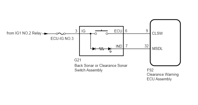
CAUTION / NOTICE / HINT
Inspect the fuses for circuits related to this system before performing the following inspection procedure.
PROCEDURE
Check the Data List for proper functioning of the back sonar or clearance sonar switch assembly (See page Audio / Visual / Telematics>PARK ASSIST / MONITORING>TOYOTA PARKING ASSIST-SENSOR SYSTEM>DATA LIST / ACTIVE TEST).
| Tester Display | Measurement Item/Range | Normal Condition | Diagnostic Note |
|---|---|---|---|
| Main Switch | Back sonar or clearance sonar switch assembly / OFF or ON | OFF: Back sonar or clearance sonar switch assembly off
ON: Back sonar or clearance sonar switch assembly on |
- |
- OK:
The GTS display changes according to operation of back sonar or clearance sonar switch assembly.
OK
NG
Remove the back sonar or clearance sonar switch assembly (See page Audio / Visual / Telematics>PARK ASSIST / MONITORING>CLEARANCE SONAR MAIN SWITCH>REMOVAL).
Inspect the back sonar or clearance sonar switch assembly (See page Audio / Visual / Telematics>PARK ASSIST / MONITORING>CLEARANCE SONAR MAIN SWITCH>INSPECTION).
OK
NG
Disconnect the F92 back sonar or clearance sonar switch assembly connector.
Disconnect the G21 clearance warning ECU assembly connector.
Measure the resistance according to the value(s) in the table below.
- Standard Resistance:
Tester Connection Condition Specified Condition G21-6 (ECU) - F92-9 (CLSW) Always Below 1 Ω G21-7 (IND) - F92-32 (MSDL) Always Below 1 Ω
Measure the voltage according to the value(s) in the table below.
- Standard Voltage:
Tester Connection Condition Specified Condition G21-3 (IG) - Body ground Engine switch on (IG) 11 to 14 V Below 1 V
OK
NG