THEFT DETERRENT / KEYLESS ENTRY ENTRY AND START SYSTEM(for Start Function) B2285 Steering Lock Position Signal Circuit Malfunction B2288 Steering Lock Signal Circuit Malfunction
DESCRIPTION
The main body ECU and the steering lock ECU are connected by a cable and the LIN communication line. These DTCs are stored when: 1) signals, transmitted through the cable and the communication line, do not match; or 2) a malfunction is detected in the circuit between the main body ECU and the steering lock ECU.
| DTC Code | Detection Condition | Trouble Area |
|---|---|---|
| B2285 | The cable and LIN information between the main body ECU and steering lock ECU is inconsistent. | ·
Main body ECU ·
Steering lock actuator assembly (steering lock ECU) ·
Harness or connector |
| B2288 | After turning the engine switch from off to on (IG), the steering wheel does not unlock for a certain period of time (the ECU unlocks the steering wheel only when it receives an unlock signal from LIN communication and the cable). | ·
Main body ECU ·
Steering lock actuator assembly (steering lock ECU) ·
Harness or connector |
WIRING DIAGRAM
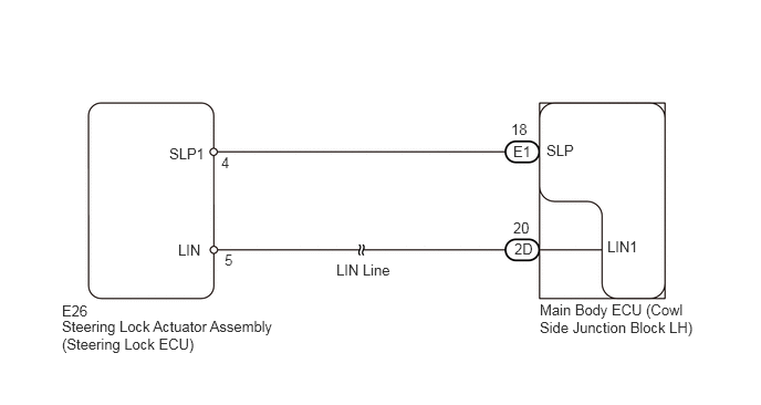
PROCEDURE
Use the Data List to check if the steering lock is functioning properly.
| Tester Display | Measurement Item/Range | Normal Condition | Diagnostic Note |
|---|---|---|---|
| Steering Unlock Switch | Steering lock condition/ON or OFF | ON: Steering unlocked
OFF: Steering locked |
- |
| Result | Proceed to |
|---|---|
| Display on the intelligent tester does not change according to steering lock position | A |
| Display on the intelligent tester changes according to steering lock position | B |
A
B
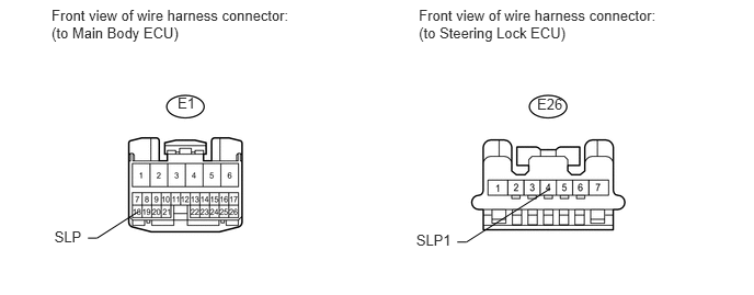
Disconnect the E1 main body ECU connector.
Disconnect the E26 steering lock ECU connector.
Measure the resistance according to the value(s) in the table below.
- Standard Resistance:
Tester Connection Condition Specified Condition E1-18 (SLP) - E26-4 (SLP1) Always Below 1 Ω E1-18 (SLP) or E26-4 (SLP1) - Body ground Always 10 kΩ or higher
OK
NG
Temporarily replace the main body ECU with a new or normally functioning one.
Check whether DTC B2285 and B2288 are output.
| Result | Proceed to |
|---|---|
| DTC not output | A |
| DTC output (for Power tilt and telescopic) | B |
| DTC output (for Manual tilt and telescopic) | C |
A
B
C