Home › Vehicle Interior › THEFT DETERRENT / KEYLESS ENTRY › THEFT DETERRENT SYSTEM (w/ Entry and Start System) › 2014.08–2015.08
RM2660E _58 Vehicle Interior _052839 THEFT DETERRENT / KEYLESS ENTRY _0255571 THEFT DETERRENT SYSTEM(w/ Entry and Start System) C

THEFT DETERRENT / KEYLESS ENTRY  THEFT DETERRENT SYSTEM(w/ Entry and Start System)  B2769  Tilt Sensor Signal Circuit Malfunction  


DESCRIPTION

The yaw rate sensor conducts a self-diagnosis immediately after power is supplied to the sensor (when the theft deterrent system is set).

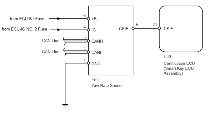
If a malfunction is detected in the CSIF-CSIF line, the certification ECU (smart key ECU assembly) stores this DTC.

DTC Code DTC Detection Condition Trouble Area
B2769 After a normal/trouble signal is output from the yaw rate sensor as the result of self-diagnosis, either of the following malfunctions is detected:
·

The CSIF-CSIF line circuit is open.

·

Reception of signals other than a normal/trouble signal.


·

Yaw rate sensor

·

Certification ECU (Smart key ECU assembly)

·

Harness or connector


WIRING DIAGRAM

B176605E02
5.457,1.802 5.826,1.949 0.369,0.147 10 E30 5.457,0.878 5.826,1.024 0.369,0.147 10 CSIF 3.965,0.878 4.334,1.024 0.369,0.147 10 CSIF 3.048,0.542 3.416,0.688 0.369,0.147 10 +B 0.331,0.542 1.539,0.688 1.208,0.147 10 from ECU-B1 Fuse 1.4,1.27 2.055,1.417 0.656,0.147 10 CAN Line 1.4,1.641 2.055,1.788 0.656,0.147 10 CAN Line 0.057,0.887 1.637,1.034 1.580,0.147 10 from ECU-IG NO. 2 Fuse 3.048,0.921 3.416,1.067 0.369,0.147 10 IG 3.048,1.296 3.481,1.443 0.434,0.147 10 CANH 3.048,1.671 3.449,1.818 0.401,0.147 10 CANL 3.048,2.046 3.416,2.193 0.369,0.147 10 GND 5.086,0.738 5.279,0.884 0.193,0.147 10 21 4.533,0.738 4.726,0.884 0.193,0.147 10 5 2.781,0.433 2.911,0.580 0.130,0.147 10 6 2.781,0.811 2.911,0.958 0.130,0.147 10 4 2.781,1.162 2.911,1.308 0.130,0.147 10 3 2.781,1.54 2.911,1.687 0.130,0.147 10 2 2.781,1.946 2.911,2.093 0.130,0.147 10 1 5.457,2.034 6.687,2.556 1.230,0.522 10 Certification ECU(Smart Key ECU Assembly) 3.048,2.573 3.416,2.720 0.369,0.147 10 E50 3.048,2.769 4.278,2.916 1.230,0.147 10 Yaw Rate Sensor

PROCEDURE

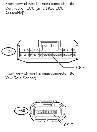
1.CHECK HARNESS AND CONNECTOR (CERTIFICATION ECU [SMART KEY ECU ASSEMBLY] - YAW RATE SENSOR)
U163937E02
1.833,1.969 2.24,2.385 2.24,2.385 2.635,2.385 true 1.865,4 2.198,4.417 true 0.188,0.042 2.76,0.531 2.573,0.49 10 false Front view of wire harness connector: (to Certification ECU [Smart Key ECU Assembly]) 0.188,2.51 2.76,2.844 2.573,0.333 10 false Front view of wire harness connector: (to Yaw Rate Sensor) 0.198,1.74 0.469,1.896 0.271,0.156 10 false E30 2.698,2.313 3.073,2.469 0.375,0.156 10 false CSIF 2.271,4.344 2.656,4.5 0.385,0.156 10 false CSIF 0.646,3.833 0.917,3.99 0.271,0.156 10 false E50

a.

Disconnect the E30 ECU connector.


b.

Disconnect the E50 sensor connector.


c.

Measure the resistance according to the value(s) in the table below.

Standard Resistance:
Tester Connection Condition Specified Condition
E30-21 (CSIF) - E50-5 (CSIF) Always Below 1 Ω
E30-21 (CSIF) or E50-5 (CSIF) - Body ground Always 10 kΩ or higher


OK

2.CHECK YAW RATE SENSOR (OPERATION)

NG

REPAIR OR REPLACE HARNESS OR CONNECTOR

2.CHECK YAW RATE SENSOR (OPERATION)
a.

Temporarily replace the yaw rate sensor that has a tilt determining function with a new or normally functioning one (See page Brake>BRAKE CONTROL / DYNAMIC CONTROL SYSTEMS>YAW RATE AND DECELERATION SENSOR (w/ VSC)>REMOVAL).


b.

Check that the system operates normally.

OK:

DTC B2769 is not output.


OK

END (YAW RATE SENSOR IS FAULTY)

NG

REPLACE CERTIFICATION ECU (SMART KEY ECU ASSEMBLY)