Home › Vehicle Interior › THEFT DETERRENT / KEYLESS ENTRY › ENTRY AND START SYSTEM(for Entry Function) › 2014.08–2015.08
RM2660E _58 Vehicle Interior _052839 THEFT DETERRENT / KEYLESS ENTRY _0255572 ENTRY AND START SYSTEM(for Entry Function) J

THEFT DETERRENT / KEYLESS ENTRY  ENTRY AND START SYSTEM(for Entry Function)  Back Door Entry Lock Function does not Operate  


DESCRIPTION

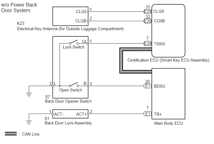
If the back door entry lock function does not operate but the back door open function operates, the communication line between the vehicle and electrical key transmitter is normal. The part at fault may be the entry lock switch circuit (certification ECU (smart key ECU assembly) → back door opener switch).

WIRING DIAGRAM
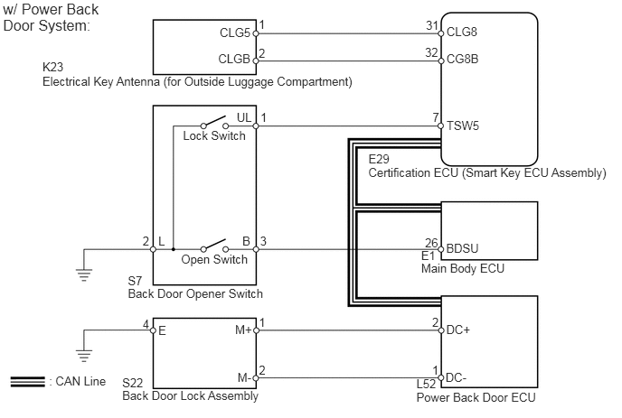
B194360E02
0.489,0.691 0.763,0.848 0.274,0.157 10 K23 2.98,0.201 3.079,0.349 0.100,0.148 10 1 2.98,0.527 3.081,0.680 0.101,0.152 10 2 4.907,0.206 5.080,0.344 0.173,0.138 10 31 4.897,0.526 5.080,0.676 0.184,0.150 10 32 5.145,0.592 5.541,0.732 0.395,0.141 10 CG8B 2.515,0.599 2.917,0.754 0.402,0.156 10 CLGB 5.145,0.279 5.530,0.420 0.385,0.141 10 CLG8 2.532,0.292 2.914,0.434 0.382,0.143 10 CLG5 4.245,1.905 7.109,2.093 2.864,0.188 10 Certification ECU (Smart Key ECU Assembly) 4.245,1.746 4.522,1.888 0.276,0.142 10 E29 4.984,1.273 5.081,1.419 0.097,0.145 10 7 5.145,1.361 5.555,1.499 0.409,0.139 10 TSW5 3.001,1.268 3.098,1.421 0.098,0.153 10 1 2.996,2.695 3.098,2.837 0.102,0.142 10 3 2.792,2.695 2.927,2.851 0.135,0.156 10 B 2.727,1.268 2.926,1.414 0.199,0.147 10 UL 4.897,2.716 5.080,2.858 0.184,0.142 10 26 5.14,2.783 5.551,2.921 0.411,0.138 10 BDSU 4.852,2.866 5.058,3.008 0.206,0.142 10 E1 4.979,3.638 5.078,3.783 0.098,0.145 10 2 5.141,3.716 5.444,3.856 0.302,0.140 10 DC+ 4.797,4.498 6.249,4.638 1.452,0.139 10 Power Back Door ECU 0.565,4.315 1.314,4.503 0.748,0.188 10 : CAN Line 1.643,2.695 1.739,2.834 0.096,0.139 10 2 1.824,2.695 1.919,2.851 0.095,0.156 10 L 1.473,3.306 3.129,3.494 1.656,0.188 10 Back Door Opener Switch 1.408,4.476 3.064,4.664 1.656,0.188 10 Back Door Lock Assembly 2.983,3.637 3.098,3.776 0.115,0.139 10 1 2.709,3.714 2.926,3.870 0.217,0.156 10 M+ 1.643,3.655 1.751,3.806 0.108,0.151 10 4 1.824,3.725 1.943,3.881 0.118,0.156 10 E 2.087,2.907 3.035,3.068 0.948,0.161 10 Open Switch 2.108,1.478 2.896,1.629 0.788,0.151 10 Lock Switch 0.489,0.852 4.207,1.009 3.718,0.157 10 Electrical Key Antenna (for Outside Luggage Compartment) 1.473,3.156 1.664,3.313 0.191,0.157 10 S7 1.408,4.335 1.713,4.492 0.305,0.157 10 S22 0.034,0 1.251,0.436 1.217,0.436 12 w/ Power Back Door System: 4.797,4.348 5.046,4.505 0.249,0.156 10 L52 4.979,4.192 5.078,4.336 0.098,0.145 10 1 5.133,4.27 5.408,4.410 0.275,0.140 10 DC- 2.983,4.191 3.098,4.329 0.115,0.139 10 2 2.737,4.268 2.926,4.424 0.190,0.156 10 M- 4.853,3.009 5.889,3.152 1.036,0.144 10 Main Body ECU

B187333E15
5.156,2.802 5.802,3.01 0.646,0.208 10 false BDSU 5.156,1.385 5.583,1.573 0.427,0.188 10 false TSW5 5.156,0.615 5.594,0.792 0.438,0.177 10 false CG8B 5.135,0.292 5.656,0.573 0.521,0.281 10 false CLG8 2.521,0.615 3.135,0.813 0.615,0.198 10 false CLGB 2.542,0.302 3.302,0.573 0.76,0.271 10 false CLG5 4.906,1.198 5.271,1.396 0.365,0.198 10 false 7 4.875,0.479 5.125,0.635 0.25,0.156 10 false 32 4.875,0.146 5.104,0.302 0.229,0.156 10 false 31 3,0.531 3.844,0.708 0.844,0.177 10 false 2 3,0.229 3.885,0.406 0.885,0.177 10 false 1 0.74,4.406 2.281,4.667 1.542,0.26 10 false CAN Line 4.865,2.646 5.229,2.865 0.365,0.219 10 false 26 5.167,4.042 6.177,4.5 1.01,0.458 10 false Main Body ECU 4.271,1.927 7.156,2.115 2.885,0.188 10 false Certification ECU (Smart Key ECU Assembly) 0.573,0.875 4.198,1.083 3.625,0.208 10 false Electrical Key Antenna (for Outside Luggage Compartment) 1.51,3.302 3.333,3.5 1.823,0.198 10 false Back Door Opener Switch 1.802,2.708 2.344,3.208 0.542,0.5 10 false L 2.104,1.49 2.917,1.719 0.813,0.229 10 false Lock Switch 1.979,2.927 2.938,3.177 0.958,0.25 10 false Open Switch 2.802,2.708 3.115,2.969 0.313,0.26 10 false B 2.75,1.302 3.875,1.979 1.125,0.677 10 false UL 1.656,2.719 2.854,3.208 1.198,0.49 10 false 2 3,2.719 3.292,3.073 0.292,0.354 10 false 3 3,1.292 4.417,1.927 1.417,0.635 10 false 1 1.5,4.031 3.25,4.229 1.75,0.198 10 false Back Door Lock Assembly 1.646,3.656 1.729,3.813 0.083,0.156 10 false 1 1.813,3.74 2.604,3.969 0.792,0.229 10 false ACT- 2.552,3.74 3.427,3.979 0.875,0.24 10 false ACT+ 3.01,3.656 3.49,3.865 0.479,0.208 10 false 2 5.156,3.74 5.792,3.917 0.635,0.177 10 false TR+ 4.906,3.51 5.844,3.729 0.938,0.219 10 false 1 4.823,1.375 5.104,1.563 0.281,0.188 10 false E29 4.823,0.302 5.146,0.49 0.323,0.188 10 false E29 4.865,3.729 5.813,4.094 0.948,0.365 10 false E1 4.865,2.792 5.604,3.219 0.74,0.427 10 false E1 0.042,0.052 1.438,0.875 1.396,0.823 12 false w/o Power Back Door System: 0.573,0.698 1.667,0.896 1.094,0.198 10 false K23 4.823,0.625 5.146,0.813 0.323,0.188 10 false E29 1.51,3.156 3.333,3.354 1.823,0.198 10 false S7 1.49,3.885 3.313,4.083 1.823,0.198 10 false S1

CAUTION / NOTICE / HINT

NOTICE:

Before performing the inspection, check that there are no problems related to the "CAN Communication System" and "LIN Communication System".


PROCEDURE

1.CHECK POWER DOOR LOCK OPERATION
a.

When the door control switch of the master switch assembly is operated, check that the locked doors unlock.

OK:

Door locks operate normally.


OK

2.CHECK VEHICLE EQUIPMENT

NG

2.CHECK VEHICLE EQUIPMENT
a.

Check if the power back door is equipped on the vehicle.

Result
Result Proceed to
w/ Power Back Door System A
w/o Power Back Door System B


A

3.CHECK POWER BACK DOOR OPERATION

B

4.READ VALUE USING INTELLIGENT TESTER (DOOR LOCK POSITION SWITCH)
3.CHECK POWER BACK DOOR OPERATION
a.

When the power back door switch is operated, check that the power back door closes.

OK:

Power back door system is normal.


Result
Result Proceed to
Power back door system is abnormal A
Power back door system is normal B


A

B

5.READ VALUE USING INTELLIGENT TESTER (BACK DOOR LOCK SWITCH)
4.READ VALUE USING INTELLIGENT TESTER (DOOR LOCK POSITION SWITCH)
a.

Connect the intelligent tester to the DLC3.


b.

Turn the engine switch on (IG).


c.

Turn the intelligent tester on.


d.

Enter the following menus: Body / Main Body / Data List.


e.

Read the Data List according to the display on the intelligent tester.

Main Body
Tester Display Measurement Item / Range Normal Condition Diagnostic Note
Back Lock Pos switch Back door lock position switch signal / ON or OFF ON: Back door is unlocked
OFF: Back door is locked
-

OK:

On the intelligent tester screen, the display changes between ON and OFF as shown in the chart above.


OK

5.READ VALUE USING INTELLIGENT TESTER (BACK DOOR LOCK SWITCH)

NG

GO TO POWER DOOR LOCK CONTROL SYSTEM (Proceed to Only Back Door LOCK/UNLOCK Functions do not Operate)

5.READ VALUE USING INTELLIGENT TESTER (BACK DOOR LOCK SWITCH)
a.

Using the intelligent tester, read the Data List.

Entry&Start
Tester Display Measurement Item/Display Normal Condition Diagnostic Note
Tr/B-Door Lock SW Back door lock switch / ON or OFF ON: Back door lock switch is pushed
OFF: Back door lock switch is not pushed
-

OK:

"ON" (switch is pushed) and "OFF" (switch is not pushed) appears on the screen.


OK

REPLACE CERTIFICATION ECU (SMART KEY ECU ASSEMBLY)

NG

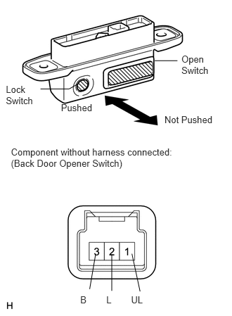
6.CHECK BACK DOOR OPENER SWITCH
a.
B185531E03
0.904,1.506 1.499,1.743 0.595,0.237 10 Pushed 2.437,1.685 3.252,2.003 0.815,0.318 10 Not Pushed 0.162,2.167 2.662,2.534 2.499,0.368 10 Component without harness connected: (Back Door Opener Switch) 1.942,4.35 2.137,4.531 0.195,0.181 10 UL 1.189,4.35 1.345,4.531 0.156,0.181 10 B 1.575,4.35 1.731,4.531 0.156,0.181 10 L 1.416,3.763 1.328,4.278 false 1.656,3.761 1.656,4.304 false 1.954,3.755 2.075,4.313 false 0.087,1.236 0.543,1.609 0.456,0.373 10 Lock Switch 2.688,0.789 3.291,1.153 0.603,0.364 10 Open Switch 0.6,1.316 1.024,1.316 1.024,1.316 1.151,1.243 false 2.628,0.898 2.292,0.898 false

Measure the resistance according to the value(s) in the table below.

Standard Resistance:
Tester Connection Switch Condition Specified Condition
1 (UL) - 2 (L) Lock switch pushed Below 1 Ω
1 (UL) - 2 (L) Lock switch not pushed 10 kΩ or higher


OK

7.CHECK HARNESS AND CONNECTOR (CERTIFICATION ECU [SMART KEY ECU ASSEMBLY] - BACK DOOR OPENER SWITCH)

NG

REPLACE BACK DOOR OPENER SWITCH

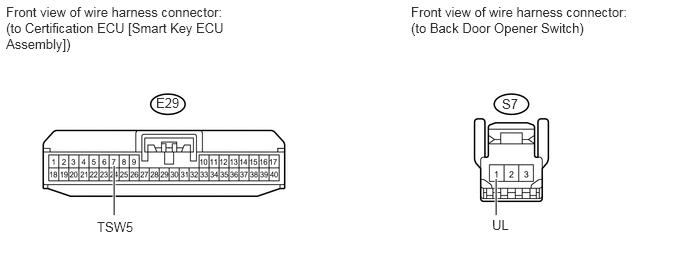
7.CHECK HARNESS AND CONNECTOR (CERTIFICATION ECU [SMART KEY ECU ASSEMBLY] - BACK DOOR OPENER SWITCH)
a.

Disconnect the E29 ECU connector.

B449335E01
1.188,1.729 1.188,2.24 true 5.167,1.865 5.167,2.24 true 0.063,0.042 2.427,0.885 2.365,0.844 10 false Front view of wire harness connector: (to Certification ECU [Smart Key ECU Assembly]) 4.281,0.042 6.646,0.885 2.365,0.844 10 false Front view of wire harness connector: (to Back Door Opener Switch) 1.625,0.99 1.927,1.156 0.302,0.167 10 false E29 5.229,1 5.531,1.167 0.302,0.167 10 false S7 1.01,2.281 1.521,2.51 0.51,0.229 10 false TSW5 5.125,2.26 5.635,2.49 0.51,0.229 10 false UL


b.

Disconnect the S7 switch connector.


c.

Measure the resistance according to the value(s) in the table below.

Standard Resistance:
Tester Connection Condition Specified Condition
E29-7 (TSW5) - S7-1 (UL) Always Below 1 Ω
E29-7 (TSW5) - Body ground Always 10 kΩ or higher


OK

REPLACE CERTIFICATION ECU (SMART KEY ECU ASSEMBLY)

NG

REPAIR OR REPLACE HARNESS OR CONNECTOR