Home › Vehicle Interior › METER / GAUGE / DISPLAY › METER / GAUGE SYSTEM › from 2015.08
RM2660E _58 Vehicle Interior _052841 METER / GAUGE / DISPLAY _0255598 METER / GAUGE SYSTEM J

METER / GAUGE / DISPLAY  METER / GAUGE SYSTEM  Entire Combination Meter does not Operate  


DESCRIPTION

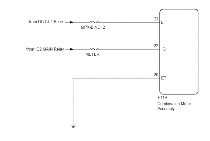
This circuit is the power source circuit for the combination meter. This circuit provides 2 power source types: one is a constant power source mainly used as a backup power source, and the other is a power source mainly used for signal transmission. The constant power source is mainly used as a backup power source for the meter CPU. However, it is also used for communication. If a voltage of 12 V is not applied to terminal IG+ when the ignition switch is ON, indicators will not operate.

WIRING DIAGRAM
E333450E04
5.385,3.25 5.792,3.427 0.406,0.177 10 false E119 5.375,3.458 6.896,3.99 1.521,0.531 10 false Combination Meter Assembly 2.917,1.771 3.635,1.948 0.719,0.177 10 false METER 2.76,0.844 3.844,1.021 1.083,0.177 10 false MPX-B NO. 2 0.99,0.656 2.198,0.906 1.208,0.25 10 false from DC CUT Fuse 5.49,0.677 5.667,0.854 0.177,0.177 10 false B 0.896,1.594 2.594,1.771 1.698,0.177 10 false from IG2 MAIN Relay 5.26,0.563 5.51,0.74 0.25,0.177 10 false 21 5.51,1.594 5.823,1.771 0.313,0.177 10 false IG+ 5.25,1.479 5.5,1.656 0.25,0.177 10 false 22 5.5,2.583 5.792,2.76 0.292,0.177 10 false ET 5.25,2.469 5.5,2.646 0.25,0.177 10 false 20

PROCEDURE

1.INSPECT FUSE (METER, MPX-B NO. 2)
a.

Remove the METER and MPX-B NO. 2 fuses from the engine room relay block.


b.

Measure the resistance according to the value(s) in the table below.

Standard Resistance:
Tester Connection Condition Specified Condition
METER fuse Always Below 1 Ω
MPX-B NO.2 fuse


OK

2.CHECK HARNESS AND CONNECTOR (COMBINATION METER ASSEMBLY - BATTERY AND BODY GROUND)

NG

REPLACE FUSE

2.CHECK HARNESS AND CONNECTOR (COMBINATION METER ASSEMBLY - BATTERY AND BODY GROUND)
a.

Disconnect the E119 combination meter assembly connector.
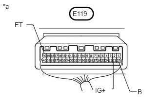

b.
U166503E02
2.917,1.958 2.771,1.958 2.771,1.958 2.531,1.323 false 0.563,0.531 0.708,0.531 0.708,0.531 0.948,1.156 false 2.271,1.906 2.417,1.906 2.417,1.906 2.417,1.323 false 1.552,0.208 1.906,0.396 0.354,0.188 10 false E119 0.063,0.052 0.417,0.24 0.354,0.188 10 false *a 2.031,1.854 2.385,2.052 0.354,0.198 10 true IG+ 0.313,0.448 0.667,0.635 0.354,0.188 10 false ET 2.938,1.885 3.292,2.073 0.354,0.188 10 false B

Measure the resistance and voltage according to the value(s) in the tables below.

Standard Resistance:
Tester Connection Condition Specified Condition
E119-20 (ET) - Body ground Always Below 1 Ω


Standard Voltage:
Tester Connection Switch Condition Specified Condition
E119-21 (B) - Body ground Always 11 to 14 V
E119-22 (IG+) - Body ground Ignition switch ON


Text in Illustration
*a Component without harness connected
(Combination Meter Assembly)


OK

REPAIR OR REPLACE HARNESS OR CONNECTOR

NG

REPLACE COMBINATION METER ASSEMBLY