Home › Vehicle Interior › HEATING / AIR CONDITIONING › AIR CONDITIONING SYSTEM (for Automatic Air Conditioning System) › 2014.08–2015.08
RM2660E _58 Vehicle Interior _052847 HEATING / AIR CONDITIONING _0255699 AIR CONDITIONING SYSTEM(for Automatic Air Conditioning System) J

HEATING / AIR CONDITIONING  AIR CONDITIONING SYSTEM(for Automatic Air Conditioning System)  Air Conditioning Compressor Magnetic Clutch Circuit  


DESCRIPTION

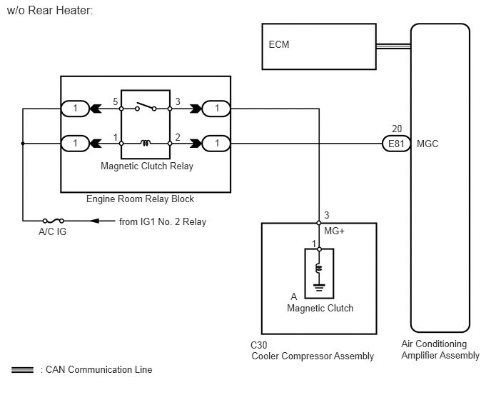
When the air conditioning amplifier assembly is turned on, a magnetic clutch on signal is sent from the MGC terminal of the air conditioning amplifier assembly. Then, the magnetic clutch relay turns on to operate the magnetic clutch.

WIRING DIAGRAM
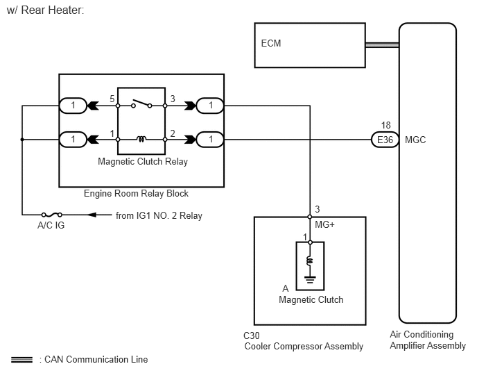
E158696E02
3.131,2.002 3.338,2.172 0.207,0.170 10 1 3.131,1.488 3.338,1.658 0.207,0.170 10 1 1.06,2.002 1.267,2.172 0.207,0.170 10 1 1.06,1.488 1.267,1.658 0.207,0.170 10 1 2.557,1.914 2.763,2.084 0.207,0.170 10 2 2.557,1.4 2.763,1.569 0.207,0.170 10 3 1.647,1.914 1.854,2.084 0.207,0.170 10 1 1.647,1.4 1.854,1.569 0.207,0.170 10 5 1.47,2.337 2.986,2.687 1.516,0.351 10 Magnetic Clutch Relay 1.259,2.81 2.971,2.992 1.712,0.182 10 Engine Room Relay Block 0.101,0.045 1.594,0.333 1.493,0.288 12 w/ Rear Heater: 0.564,3.294 1.033,3.477 0.468,0.184 10 A/C IG 1.74,3.145 3.116,3.301 1.376,0.156 10 from IG1 NO. 2 Relay 0.59,5.307 2.399,5.463 1.810,0.156 10 : CAN Communication Line 4.731,3.053 4.871,3.212 0.140,0.159 10 3 4.545,3.468 4.704,3.627 0.159,0.159 10 1 4.244,4.235 4.449,4.439 0.205,0.205 10 A 3.654,4.948 3.976,5.111 0.323,0.163 10 C30 3.67,5.107 5.566,5.273 1.896,0.166 10 Cooler Compressor Assembly 4.189,4.408 5.226,4.548 1.037,0.140 10 Magnetic Clutch 5.667,2.011 6.002,2.152 0.336,0.141 10 E36 6.084,2.014 6.476,2.156 0.392,0.142 10 MGC 3.922,0.564 4.314,0.706 0.392,0.142 10 ECM 5.721,1.788 5.946,1.982 0.225,0.194 10 18 5.859,4.931 7.078,5.281 1.219,0.350 10 Air Conditioning Amplifier Assembly 4.731,3.283 5.089,3.438 0.357,0.155 10 MG+

E158696E03
3.131,2.002 3.338,2.172 0.207,0.170 10 1 3.131,1.488 3.338,1.658 0.207,0.170 10 1 1.06,2.002 1.267,2.172 0.207,0.170 10 1 1.06,1.488 1.267,1.658 0.207,0.170 10 1 2.557,1.914 2.763,2.084 0.207,0.170 10 2 2.557,1.4 2.763,1.569 0.207,0.170 10 3 1.647,1.914 1.854,2.084 0.207,0.170 10 1 1.647,1.4 1.854,1.569 0.207,0.170 10 5 1.47,2.337 2.986,2.687 1.516,0.351 10 Magnetic Clutch Relay 1.259,2.81 2.971,2.992 1.712,0.182 10 Engine Room Relay Block 0.101,0.045 1.594,0.333 1.493,0.288 12 w/o Rear Heater: 0.564,3.294 1.033,3.477 0.468,0.184 10 A/C IG 1.74,3.145 3.116,3.301 1.376,0.156 10 from IG1 No. 2 Relay 0.59,5.307 2.399,5.463 1.810,0.156 10 : CAN Communication Line 4.731,3.053 4.871,3.212 0.140,0.159 10 3 4.545,3.468 4.704,3.627 0.159,0.159 10 1 4.244,4.235 4.449,4.439 0.205,0.205 10 A 3.654,4.948 3.976,5.111 0.323,0.163 10 C30 3.67,5.107 5.566,5.273 1.896,0.166 10 Cooler Compressor Assembly 4.189,4.408 5.226,4.548 1.037,0.140 10 Magnetic Clutch 5.667,2.011 6.002,2.152 0.336,0.141 10 E81 6.084,2.014 6.476,2.156 0.392,0.142 10 MGC 3.922,0.564 4.314,0.706 0.392,0.142 10 ECM 5.721,1.788 5.946,1.982 0.225,0.194 10 20 5.859,4.931 7.078,5.281 1.219,0.350 10 Air Conditioning Amplifier Assembly 4.731,3.283 5.089,3.438 0.357,0.155 10 MG+

PROCEDURE

1.CHECK CAN COMMUNICATION SYSTEM
a.

Check for CAN communication system DTCs related to the air conditioning system.

Result
Result Proceed to
CAN DTC is not output A
CAN DTC is output (for LHD) B
CAN DTC is output (for RHD) C


A

2.READ VALUE USING INTELLIGENT TESTER (A/C SIGNAL)

B

C

2.READ VALUE USING INTELLIGENT TESTER (A/C SIGNAL)
a.

Use the Data List to check if the A/C switch is functioning properly.

Engine
Tester Display Measurement Item/Range Normal Condition Diagnostic Note
A/C Signal A/C signal / ON or OFF ON: A/C switch on
OFF: A/C switch off
-

OK:

The display is as specified in the normal condition.


OK

NG

3.INSPECT FUSE (A/C IG)
a.

Remove the A/C IG fuse from the cowl side junction block LH.


b.

Measure the resistance according to the value(s) in the table below.

Standard Resistance:
Tester Connection Condition Specified Condition
A/C IG fuse Always Below 1 Ω


OK

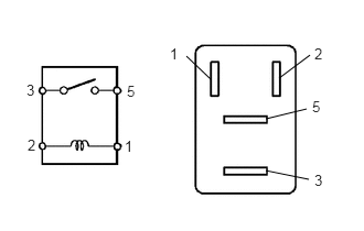
4.INSPECT MAGNETIC CLUTCH RELAY

NG

REPLACE FUSE (A/C IG)

4.INSPECT MAGNETIC CLUTCH RELAY
a.
B449346E02
1.76,0.531 1.99,0.75 false 2.635,0.74 2.927,0.521 false 2.51,1.125 2.896,1.031 false 2.51,1.615 2.917,1.698 false 0.25,0.771 0.406,0.969 0.156,0.198 10 false 3 1.177,1.302 1.333,1.5 0.156,0.198 10 false 1 1.198,0.781 1.354,0.979 0.156,0.198 10 false 5 0.26,1.292 0.417,1.49 0.156,0.198 10 false 2 1.604,0.427 1.76,0.625 0.156,0.198 10 false 1 2.969,0.427 3.125,0.625 0.156,0.198 10 false 2 2.948,0.927 3.104,1.125 0.156,0.198 10 false 5 2.969,1.625 3.125,1.823 0.156,0.198 10 false 3

Remove the magnetic clutch relay from the engine room relay block.


b.

Measure the resistance according to the value(s) in the table below.

Standard Resistance:
Tester Connection Condition Specified Condition
3 - 5 Voltage not applied to terminals 1 and 2 10 kΩ or higher
3 - 5 Voltage applied to terminals 1 and 2 Below 1 Ω


c.

Install the magnetic clutch relay to the engine room relay block.


OK

5.CHECK HARNESS AND CONNECTOR (AIR CONDITIONING AMPLIFIER - BATTERY)

NG

REPLACE MAGNETIC CLUTCH RELAY

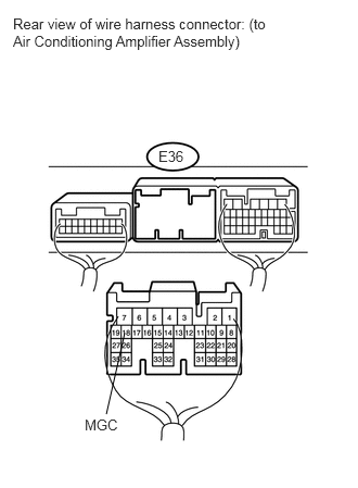
5.CHECK HARNESS AND CONNECTOR (AIR CONDITIONING AMPLIFIER - BATTERY)
a.
U165944E02
1.198,3.188 1.021,3.969 false 0.125,0.146 2.563,0.521 2.438,0.375 10 false Rear view of wire harness connector: (to Air Conditioning Amplifier Assembly) 1.521,1.417 1.865,1.604 0.344,0.188 10 false E36 0.813,3.99 1.156,4.167 0.344,0.177 10 false MGC

w/ Rear Heater

i.

Disconnect the E36 amplifier connector.


ii.

Measure the voltage according to the value(s) in the table below.

Standard Voltage:
Tester Connection Switch Condition Specified Condition
E36-18 (MGC) - Body ground Engine switch off Below 1 V
E36-18 (MGC) - Body ground Engine switch on (IG) 11 to 14 V
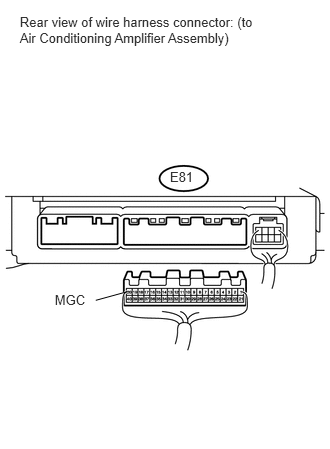


b.
U166046E01
0.206,0.148 2.695,0.498 2.489,0.350 10 Rear view of wire harness connector: (to Air Conditioning Amplifier Assembly) 1.77,1.757 2.141,1.954 0.371,0.198 10 E81 0.57,3.037 0.925,3.187 0.356,0.150 10 MGC 1.324,3.038 0.997,3.128 false

w/o Rear Heater

i.

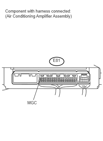
Disconnect the E81 amplifier connector.


ii.

Measure the voltage according to the value(s) in the table below.

Standard Voltage:
Tester Connection Switch Condition Specified Condition
E81-20 (MGC) - Body ground Engine switch off Below 1 V
E81-20 (MGC) - Body ground Engine switch on (IG) 11 to 14 V


OK

6.INSPECT AIR CONDITIONING AMPLIFIER ASSEMBLY

NG

REPAIR OR REPLACE HARNESS OR CONNECTOR

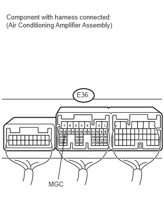
6.INSPECT AIR CONDITIONING AMPLIFIER ASSEMBLY
a.
U165955E01
0.131,0.272 2.455,0.692 2.325,0.420 10 Component with harness connected: (Air Conditioning Amplifier Assembly) 1.608,1.892 1.963,2.078 0.355,0.186 10 E36 1.016,3.761 1.389,3.905 0.373,0.144 10 MGC 1.367,2.779 1.22,3.745 false

w/ Rear Heater

i.

Reconnect the E36 amplifier connector.


ii.

Measure the voltage according to the value(s) in the table below.

Standard Voltage:
Tester Connection Switch Condition Specified Condition
E36-18 (MGC) - Body ground Engine switch on (IG)
A/C switch off
11 to 14 V
E36-18 (MGC) - Body ground Engine switch on (IG)
A/C switch on
Below 1 V


b.
U166056E01
0.174,0.282 2.518,0.650 2.344,0.368 10 Component with harness connected: (Air Conditioning Amplifier Assembly) 1.768,1.919 2.035,2.088 0.267,0.170 10 E81 0.911,3.326 1.317,3.487 0.406,0.161 10 MGC 1.353,2.606 1.114,3.314 false

w/o Rear Heater

i.

Reconnect the E81 amplifier connector.


ii.

Measure the voltage according to the value(s) in the table below.

Standard Voltage:
Tester Connection Switch Condition Specified Condition
E81-20 (MGC) - Body ground Engine switch on (IG)
A/C switch off
11 to 14 V
E81-20 (MGC) - Body ground Engine switch on (IG)
A/C switch on
Below 1 V


OK

7.INSPECT COOLER COMPRESSOR ASSEMBLY

NG

REPLACE AIR CONDITIONING AMPLIFIER ASSEMBLY

7.INSPECT COOLER COMPRESSOR ASSEMBLY
a.
U166059E02
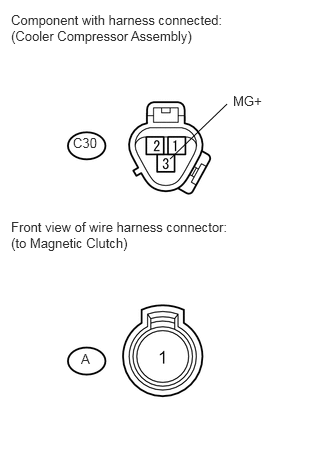
2.365,1.083 1.771,1.656 false 0.115,0.125 2.385,0.479 2.271,0.354 10 false Component with harness connected: (Cooler Compressor Assembly) 0.76,1.406 1.115,1.573 0.354,0.167 10 false C30 2.427,0.969 2.771,1.156 0.344,0.188 10 false MG+ 0.115,2.281 2.49,2.646 2.375,0.365 10 false Front view of wire harness connector: (to Magnetic Clutch) 0.844,3.656 1.021,3.823 0.177,0.167 10 false A

Disconnect the C30 compressor connector.


b.

Disconnect the A magnetic clutch connector.


c.

Measure the resistance according to the value(s) in the table below.

Standard Resistance:
Tester Connection Condition Specified Condition
C30-3 (MG+) - A-1 Always Below 1 Ω
C30-3 (MG+) - Body ground Always 10 kΩ or higher


OK

8.INSPECT MAGNETIC CLUTCH

NG

8.INSPECT MAGNETIC CLUTCH
a.
U165957E02
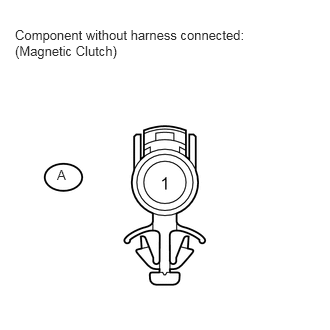
0.156,0.281 2.635,0.646 2.479,0.365 10 false Component without harness connected: (Magnetic Clutch) 0.594,1.74 0.781,1.927 0.188,0.188 10 false A

Measure the resistance according to the value(s) in the table below.

Standard Resistance:
Tester Connection Condition Specified Condition
A-1 - Body ground 20°C (68°F) 3.4 to 3.8 Ω


b.

When connector terminal A-1 is connected to the positive (+) battery terminal, check that the following occurs: 1) the operating sound of the magnetic clutch can be heard, and 2) the hub and rotor of the magnetic clutch lock.


OK

9.CHECK HARNESS AND CONNECTOR (ENGINE ROOM RELAY BLOCK - BATTERY)

NG

REPLACE MAGNETIC CLUTCH

9.CHECK HARNESS AND CONNECTOR (ENGINE ROOM RELAY BLOCK - BATTERY)
a.
E157043E05
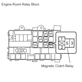
2.813,1.979 2.938,2.635 false 0.063,0.094 1.854,0.354 1.792,0.26 10 false Engine Room Relay Block: 1.729,2.677 3.146,2.885 1.417,0.208 10 false Magnetic Clutch Relay

Remove the magnetic clutch relay from the engine room relay block.


b.

Measure the voltage according to the value(s) in the table below.

Standard Voltage:
Tester Connection Switch Condition Specified Condition
Relay block magnetic clutch relay terminal 5 - Body ground Engine switch on (IG) 11 to 14 V
Relay block magnetic clutch relay terminal 1 - Body ground Engine switch on (IG) 11 to 14 V


OK

REPAIR OR REPLACE HARNESS OR CONNECTOR (ENGINE ROOM RELAY BLOCK - COOLER COMPRESSOR)

NG

REPAIR OR REPLACE HARNESS OR CONNECTOR (ENGINE ROOM RELAY BLOCK - BATTERY)