Home › Vehicle Interior › HEATING / AIR CONDITIONING › AIR CONDITIONING SYSTEM (for Automatic Air Conditioning System) › 2014.08–2015.08
RM2660E _58 Vehicle Interior _052847 HEATING / AIR CONDITIONING _0255699 AIR CONDITIONING SYSTEM(for Automatic Air Conditioning System) C

HEATING / AIR CONDITIONING  AIR CONDITIONING SYSTEM(for Automatic Air Conditioning System)  B1419/19  Rear Room Temperature Sensor Circuit  


DESCRIPTION

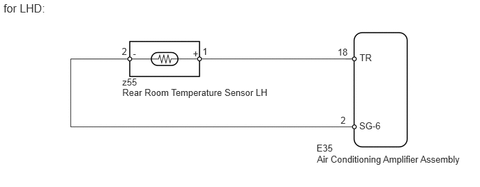
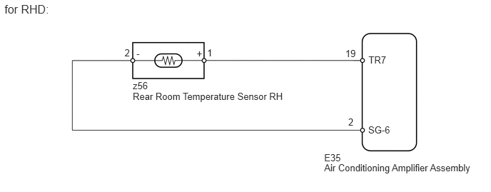
The rear room temperature sensor LH*1 or RH*2 (for driver side) is installed in the rear quarter trim board LH*1 or RH*2 to detect the rear room temperature and control the heater and air conditioner "auto" mode. The resistance of the rear room temperature sensor LH*1 or RH*2 changes in accordance with the rear room temperature for the LH*1 or RH*2 seat. As the temperature decreases, the resistance increases. As the temperature increases, the resistance decreases.

The air conditioning amplifier assembly applies a voltage (5 V) to the rear room temperature sensor LH*1 or RH*2 and reads voltage changes as changes in the resistance of the rear room temperature sensor LH*1 or RH*2.

DTC Code DTC Detection Condition Trouble Area
B1419/19 An open or short in the rear room temperature sensor LH*1 or RH*2 circuit.
·

Rear room temperature sensor LH*1

·

Rear room temperature sensor RH*2

·

Harness or connector between rear room temperature sensor LH and air conditioning amplifier assembly*1

·

Harness or connector between rear room temperature sensor RH and air conditioning amplifier assembly*2

·

Air conditioning amplifier assembly


HINT:

*1: for LHD

*2: for RHD


WIRING DIAGRAM

E156584E40
1.818,0.69 1.944,0.851 0.126,0.161 10 2 1.984,0.718 2.110,0.879 0.126,0.161 10 - 2.88,0.718 3.006,0.879 0.126,0.161 10 + 1.826,1.149 2.197,1.310 0.370,0.161 10 z55 1.826,1.307 4.096,1.467 2.270,0.161 10 Rear Room Temperature Sensor LH 4.732,2.303 6.994,2.464 2.262,0.161 10 Air Conditioning Amplifier Assembly 3.023,0.69 3.149,0.851 0.126,0.161 10 1 5.039,0.698 5.221,0.858 0.182,0.161 10 18 5.368,0.784 5.673,0.945 0.305,0.161 10 TR 5.364,1.807 5.885,1.968 0.521,0.161 10 SG-6 4.726,2.139 5.031,2.300 0.305,0.161 10 E35 5.085,1.719 5.267,1.880 0.182,0.161 10 2 0.052,0.026 0.773,0.226 0.721,0.200 12 for LHD:

E156584E41
1.818,0.69 1.944,0.851 0.126,0.161 10 2 1.991,0.702 2.117,0.863 0.126,0.161 10 - 2.87,0.702 2.996,0.863 0.126,0.161 10 + 1.938,1.165 2.309,1.326 0.370,0.161 10 z56 1.938,1.323 4.359,1.484 2.420,0.161 10 Rear Room Temperature Sensor RH 4.732,2.368 7.067,2.529 2.334,0.161 10 Air Conditioning Amplifier Assembly 3.023,0.69 3.149,0.851 0.126,0.161 10 1 5.04,0.698 5.221,0.858 0.182,0.161 10 19 5.379,0.79 5.684,0.951 0.305,0.161 10 TR7 5.375,1.813 5.896,1.973 0.521,0.161 10 SG-6 4.732,2.215 5.037,2.376 0.305,0.161 10 E35 5.083,1.703 5.265,1.863 0.182,0.161 10 2 0.065,0.034 0.823,0.283 0.758,0.248 12 for RHD:

PROCEDURE

1.READ VALUE USING INTELLIGENT TESTER (AIR CONDITIONER)
a.

Use the Data List to check if the rear room temperature sensor LH*1 or RH*2 is functioning properly.

Air Conditioner
Tester Display Measurement Item/Range Normal Condition Diagnostic Note
Room Temp Sensor (Rear) Rear room temperature sensor for LH*1 or RH*2 /
Min.: -6.5°C (20.3°F)
Max.: 57.25°C (135.05°F)
Actual rear room temperature for LH*1 or RH*2 displayed Open in the circuit: -6.5°C (20.3°F).
Short in the circuit: 57.25°C (135.05°F).

HINT:

*1: for LHD

*2: for RHD


OK:

The display is as specified in the normal condition.


OK

REPLACE AIR CONDITIONING AMPLIFIER ASSEMBLY

NG

2.INSPECT REAR ROOM TEMPERATURE SENSOR
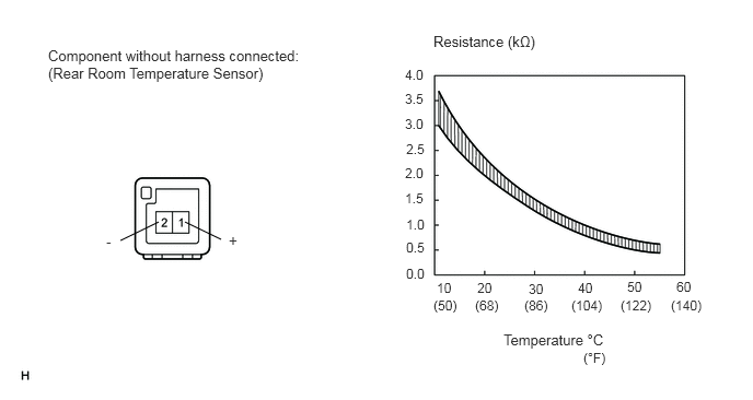
E345463E03
1.76,2.115 2.104,2.281 false 1.51,2.115 1.146,2.292 false 0.458,0.448 2.896,0.823 2.438,0.375 10 false Component without harness connected: (Rear Room Temperature Sensor) 4.125,0.313 5.146,0.5 1.021,0.188 10 false Resistance (kΩ) 3.854,0.635 4.073,0.813 0.219,0.177 9 false 4.0 3.865,2.531 4.073,2.698 0.208,0.167 9 false 0.0 3.865,2.281 4.073,2.448 0.208,0.167 9 false 0.5 3.865,2.063 4.073,2.229 0.208,0.167 9 false 1.0 3.854,1.813 4.063,1.979 0.208,0.167 9 false 1.5 3.854,1.573 4.063,1.74 0.208,0.167 9 false 2.0 3.865,1.344 4.073,1.51 0.208,0.167 9 false 2.5 3.854,1.104 4.063,1.271 0.208,0.167 9 false 3.0 3.854,0.865 4.063,1.031 0.208,0.167 9 false 3.5 4.156,2.667 4.365,2.833 0.208,0.167 9 false 10 4.542,2.667 4.75,2.833 0.208,0.167 9 false 20 5.031,2.677 5.24,2.844 0.208,0.167 9 false 30 5.5,2.667 5.708,2.833 0.208,0.167 9 false 40 5.969,2.656 6.177,2.823 0.208,0.167 9 false 50 6.438,2.656 6.646,2.823 0.208,0.167 9 false 60 4.125,2.833 4.375,3 0.25,0.167 9 false (50) 4.521,2.833 4.771,3 0.25,0.167 9 false (68) 4.99,2.833 5.24,3 0.25,0.167 9 false (86) 5.438,2.833 5.771,3 0.333,0.167 9 false (104) 5.906,2.833 6.24,3 0.333,0.167 9 false (122) 6.385,2.833 6.719,3 0.333,0.167 9 false (140) 4.792,3.156 5.76,3.375 0.969,0.219 10 false Temperature °C 5.552,3.333 5.781,3.677 0.229,0.344 9 false (°F) 1.01,2.219 1.167,2.417 0.156,0.198 10 false - 2.177,2.208 2.333,2.406 0.156,0.198 10 false +

a.

for LHD

i.


b.

for RHD

i.


c.

Measure the resistance according to the value(s) in the table below.

Standard Resistance:
Tester Connection Condition Specified Condition
1 (+) - 2 (-) 10°C (50°F) 3.00 to 3.73 kΩ
15°C (59°F) 2.45 to 2.88 kΩ
20°C (68°F) 1.95 to 2.30 kΩ
25°C (77°F) 1.60 to 1.80 kΩ
30°C (86°F) 1.28 to 1.47 kΩ
35°C (95°F) 1.00 to 1.22 kΩ
40°C (104°F) 0.80 to 1.00 kΩ
45°C (113°F) 0.65 to 0.85 kΩ
50°C (122°F) 0.50 to 0.70 kΩ
55°C (131°F) 0.44 to 0.60 kΩ
60°C (140°F) 0.36 to 0.50 kΩ


NOTICE:

Even slightly touching the sensor may change the resistance value. Be sure to hold the connector of the sensor.


HINT:

As the temperature increases, the resistance decreases (see the graph).


Result
Result Proceed to
OK A
NG (for LHD) B
NG (for RHD) C


A

3.CHECK HARNESS AND CONNECTOR (REAR ROOM TEMPERATURE SENSOR - AIR CONDITIONING AMPLIFIER)

B

C

3.CHECK HARNESS AND CONNECTOR (REAR ROOM TEMPERATURE SENSOR - AIR CONDITIONING AMPLIFIER)
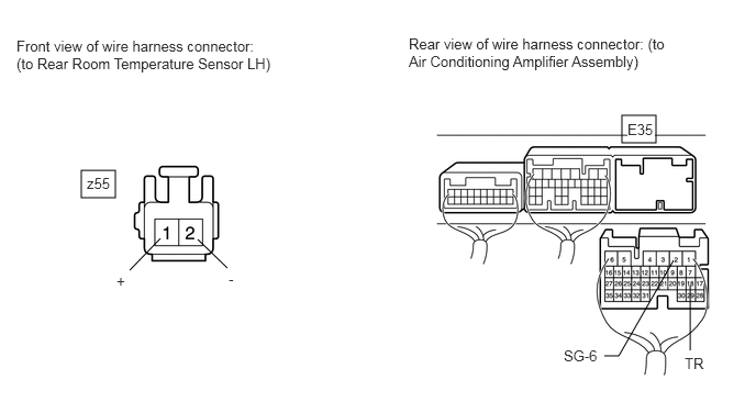
E349551E01
0.771,1.615 1.094,1.875 0.323,0.26 5.896,1.094 6.219,1.354 0.323,0.26 1.229,2.563 1.521,2.26 false 2.156,2.542 1.875,2.271 false 5.729,3.375 5.865,3.375 5.865,3.375 6.385,2.469 false 6.542,3.323 6.542,2.708 false 0.156,0.354 2.583,0.75 2.427,0.396 10 false Front view of wire harness connector: (to Rear Room Temperature Sensor LH) 3.875,0.333 6.313,0.729 2.438,0.396 10 false Rear view of wire harness connector: (to Air Conditioning Amplifier Assembly) 0.823,1.656 1.135,1.854 0.313,0.198 10 false z55 1.104,2.583 1.417,2.781 0.313,0.198 10 false + 2.167,2.563 2.479,2.76 0.313,0.198 10 false - 5.948,1.146 6.208,1.344 0.26,0.198 10 true E35 5.344,3.292 5.76,3.5 0.417,0.208 10 false SG-6 6.49,3.365 6.906,3.573 0.417,0.208 10 false TR

a.

for LHD

i.

Disconnect the z55 sensor connector.


ii.

Disconnect the E35 amplifier connector.


iii.

Measure the resistance according to the value(s) in the table below.

Standard Resistance:
Tester Connection Condition Specified Condition
z55-1 (+) - E35-18 (TR) Always Below 1 Ω
z55-2 (-) - E35-2 (SG-6)
E35-18 (TR) - Body ground Always 10 kΩ or higher
E35-2 (SG-6) - Body ground


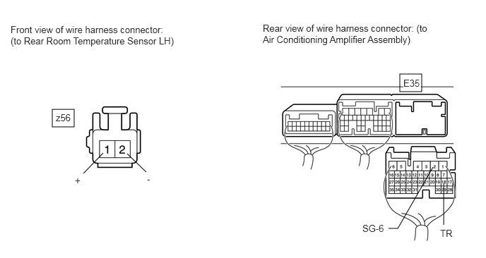
b.

for RHD

E349551E02
0.771,1.615 1.094,1.875 0.323,0.26 5.896,1.094 6.219,1.354 0.323,0.26 1.229,2.563 1.521,2.26 false 2.156,2.542 1.875,2.271 false 5.729,3.375 5.865,3.375 5.865,3.375 6.385,2.469 false 6.542,3.323 6.542,2.708 false 0.156,0.354 2.583,0.75 2.427,0.396 10 false Front view of wire harness connector: (to Rear Room Temperature Sensor LH) 3.875,0.333 6.313,0.729 2.438,0.396 10 false Rear view of wire harness connector: (to Air Conditioning Amplifier Assembly) 0.823,1.656 1.135,1.854 0.313,0.198 10 false z56 1.104,2.583 1.417,2.781 0.313,0.198 10 false + 2.167,2.563 2.479,2.76 0.313,0.198 10 false - 5.948,1.146 6.208,1.344 0.26,0.198 10 true E35 5.344,3.292 5.76,3.5 0.417,0.208 10 false SG-6 6.49,3.365 6.906,3.573 0.417,0.208 10 false TR

i.

Disconnect the z56 sensor connector.


ii.

Disconnect the E35 amplifier connector.


iii.

Measure the resistance according to the value(s) in the table below.

Standard Resistance:
Tester Connection Condition Specified Condition
z56-2 (-) - E35-2 (SG-6) Always Below 1 Ω
z56-1 (+) - E35-19 (TR7)
E35-2 (SG-6) - Body ground Always 10 kΩ or higher
E35-19 (TR7) - Body ground


OK

REPLACE AIR CONDITIONING AMPLIFIER ASSEMBLY

NG

REPAIR OR REPLACE HARNESS OR CONNECTOR