Home › Vehicle Interior › HEATING / AIR CONDITIONING › AIR CONDITIONING SYSTEM(for Manual Air Conditioning System) › 2014.08–2015.08
RM2660E _58 Vehicle Interior _052847 HEATING / AIR CONDITIONING _0255703 AIR CONDITIONING SYSTEM(for Manual Air Conditioning System) J

HEATING / AIR CONDITIONING  AIR CONDITIONING SYSTEM(for Manual Air Conditioning System)  PTC Heater Circuit  


DESCRIPTION

PTC heater relays are closed in accordance with signals from the air conditioning amplifier assembly and power is supplied to the quick heater assembly installed on the radiator heater unit.

WIRING DIAGRAM
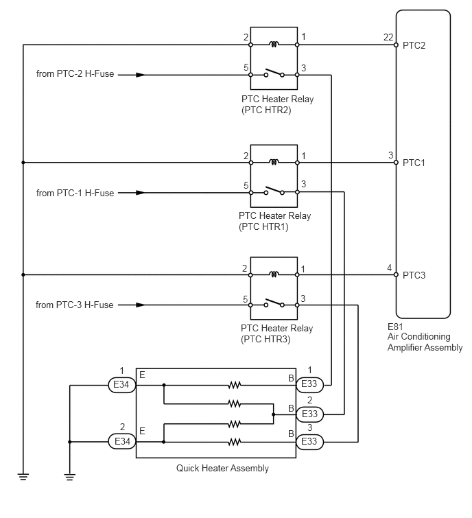
U166095E02
3.698,2.729 3.865,2.927 0.167,0.198 10 false 5 3.698,2.281 3.844,2.458 0.146,0.177 10 false 2 4.573,2.281 4.708,2.448 0.135,0.167 10 false 1 4.573,2.708 4.698,2.906 0.125,0.198 10 false 3 6.115,2.385 6.51,2.563 0.396,0.177 10 false PTC1 6.115,0.604 6.51,0.781 0.396,0.177 10 false PTC2 6.115,4.094 6.51,4.271 0.396,0.177 10 false PTC3 5.896,2.271 6.073,2.49 0.177,0.219 10 false 3 5.823,0.479 6.031,0.667 0.208,0.188 10 false 22 5.875,3.979 6.042,4.167 0.167,0.188 10 false 4 3.698,0.938 3.802,1.135 0.104,0.198 10 false 5 3.698,0.479 3.833,0.677 0.135,0.198 10 false 2 4.573,0.469 4.698,0.635 0.125,0.167 10 false 1 4.573,0.948 4.698,1.146 0.125,0.198 10 false 3 3.656,4.896 4.792,5.271 1.135,0.375 10 false PTC Heater Relay (PTC HTR3) 3.667,1.417 4.823,1.802 1.156,0.385 10 false PTC Heater Relay (PTC HTR2) 3.625,3.188 4.771,3.552 1.146,0.365 10 false PTC Heater Relay (PTC HTR1) 0.542,4.542 1.802,4.74 1.26,0.198 10 false from PTC-3 H-Fuse 0.552,1.031 1.813,1.229 1.26,0.198 10 false from PTC-2 H-Fuse 0.552,2.844 1.813,3.063 1.26,0.219 10 false from PTC-1 H-Fuse 5.885,4.875 6.188,5.031 0.302,0.156 10 false E81 5.885,5.021 7.094,5.365 1.208,0.344 10 false Air Conditioning Amplifier Assembly 4.573,5.74 4.854,5.917 0.281,0.177 10 false E33 4.583,6.198 4.865,6.375 0.281,0.177 10 false E33 4.573,6.615 4.854,6.792 0.281,0.177 10 false E33 1.719,5.75 2,5.927 0.281,0.177 10 false E34 1.74,6.615 2.021,6.792 0.281,0.177 10 false E34 1.823,6.396 1.948,6.542 0.125,0.146 10 false 2 1.813,5.542 1.938,5.688 0.125,0.146 10 false 1 4.667,5.531 4.792,5.677 0.125,0.146 10 false 1 4.667,5.99 4.792,6.135 0.125,0.146 10 false 2 4.667,6.406 4.792,6.552 0.125,0.146 10 false 3 4.375,5.656 4.49,5.844 0.115,0.188 10 false B 4.375,6.115 4.49,6.302 0.115,0.188 10 false B 4.375,6.5 4.49,6.688 0.115,0.188 10 false B 2.115,6.458 2.229,6.646 0.115,0.188 10 false E 2.115,5.604 2.229,5.792 0.115,0.188 10 false E 2.677,7.021 4.25,7.25 1.573,0.229 10 false Quick Heater Assembly 3.688,4.458 3.802,4.656 0.115,0.198 10 false 5 3.677,3.99 3.833,4.208 0.156,0.219 10 false 2 4.563,4 4.698,4.188 0.135,0.188 10 false 1 4.563,4.448 4.688,4.625 0.125,0.177 10 false 3

CAUTION / NOTICE / HINT

NOTICE:

Inspect the fuses and relays for circuits related to this system before performing the following inspection procedure.


PROCEDURE
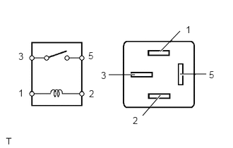
1.INSPECT PTC HEATER RELAY (PTC HTR1, PTC HTR2, PTC HTR3)
a.
E345469E01
2.365,0.76 2.656,0.458 false 2.656,1.094 3.042,1.094 false 2.104,1.708 2.365,1.406 false 1.604,1.104 1.99,1.104 false 0.271,0.75 0.385,0.938 0.115,0.188 10 false 3 0.271,1.292 0.385,1.479 0.115,0.188 10 false 1 1.302,0.74 1.417,0.927 0.115,0.188 10 false 5 1.313,1.302 1.427,1.49 0.115,0.188 10 false 2 2.74,0.354 2.854,0.542 0.115,0.188 10 false 1 3.083,1.021 3.198,1.208 0.115,0.188 10 false 5 1.958,1.698 2.073,1.885 0.115,0.188 10 false 2 1.49,1.031 1.604,1.219 0.115,0.188 10 false 3

Remove the PTC heater relays from the engine room relay block and junction block assembly.


b.

Measure the resistance according to the value(s) in the table below.

Standard Resistance:
Tester Connection Condition Specified Condition
3 - 5 Battery voltage is not applied between terminals 1 and 2 10 kΩ or higher
Battery voltage is applied between terminals 1 and 2 Below 1 Ω


OK

2.CHECK HARNESS AND CONNECTOR (PTC HEATER RELAY - BATTERY)

NG

REPLACE PTC HEATER RELAY (PTC HTR1, PTC HTR2, PTC HTR3)

2.CHECK HARNESS AND CONNECTOR (PTC HEATER RELAY - BATTERY)
a.
E234132E02
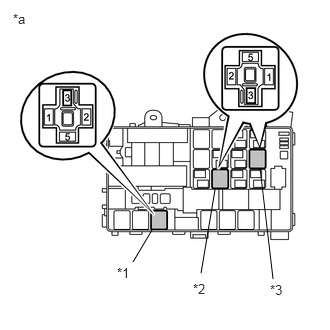
1.583,2.396 1.385,2.729 false 2.24,1.969 2.094,2.844 false 2.708,1.75 2.844,2.906 false 0.135,0.115 0.375,0.323 0.24,0.208 10 false *a 1.219,2.76 1.458,2.969 0.24,0.208 10 false *1 2.01,2.927 2.25,3.135 0.24,0.208 10 false *2 2.813,2.938 3.052,3.146 0.24,0.208 10 false *3

Remove the PTC heater relays from the engine room relay block and junction block assembly.


b.

Measure the voltage according to the value(s) in the table below.

Standard Voltage:
Tester Connection Condition Specified Condition
PTC HTR1 relay terminal 5 - Body ground Always 11 to 14 V
PTC HTR2 relay terminal 5 - Body ground
PTC HTR3 relay terminal 5 - Body ground


Text in Illustration
*a Component without relay installed
(Engine Room Relay Block and Junction Block Assembly)
*1 PTC Heater Relay (PTC HTR3)
*2 PTC Heater Relay (PTC HTR2)
*3 PTC Heater Relay (PTC HTR1)


OK

3.CHECK HARNESS AND CONNECTOR (PTC HEATER RELAY - AIR CONDITIONING AMPLIFIER AND BODY GROUND)

NG

REPAIR OR REPLACE HARNESS OR CONNECTOR

3.CHECK HARNESS AND CONNECTOR (PTC HEATER RELAY - AIR CONDITIONING AMPLIFIER AND BODY GROUND)
a.

Remove the PTC heater relays from the engine room relay block and junction block assembly.


b.

Disconnect the E81 air conditioning amplifier assembly connector.


c.

Measure the resistance according to the value(s) in the table below.

Standard Resistance:
Tester Connection Condition Specified Condition
PTC HTR1 relay terminal 1 - E81-3 (PTC1) Always Below 1 Ω
PTC HTR2 relay terminal 1 - E81-22 (PTC2)
PTC HTR3 relay terminal 1 - E81-4 (PTC3)
PTC HTR1 relay terminal 1 - Body ground Always 10 kΩ or higher
PTC HTR2 relay terminal 1 - Body ground
PTC HTR3 relay terminal 1 - Body ground


d.

Measure the resistance according to the value(s) in the table below.

Standard Resistance:
Tester Connection Condition Specified Condition
PTC HTR1 relay terminal 2 - Body ground Always Below 1 Ω
PTC HTR2 relay terminal 2 - Body ground
PTC HTR3 relay terminal 2 - Body ground


OK

4.CHECK HARNESS AND CONNECTOR (PTC HEATER RELAY - QUICK HEATER)

NG

REPAIR OR REPLACE HARNESS OR CONNECTOR

4.CHECK HARNESS AND CONNECTOR (PTC HEATER RELAY - QUICK HEATER)
a.

Remove the PTC heater relays from the engine room relay block and junction block assembly.


b.

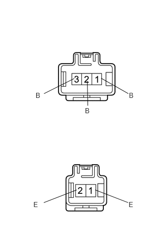
Disconnect the E33 quick heater assembly connector.


c.

Measure the resistance according to the value(s) in the table below.

Standard Resistance:
Tester Connection Condition Specified Condition
PTC HTR1 relay terminal 3 - E33-2 (B) Always Below 1 Ω
PTC HTR2 relay terminal 3 - E33-1 (B)
PTC HTR3 relay terminal 3 - E33-3 (B)
PTC HTR1 relay terminal 3 - Body ground Always 10 kΩ or higher
PTC HTR2 relay terminal 3 - Body ground
PTC HTR3 relay terminal 3 - Body ground


OK

5.CHECK HARNESS AND CONNECTOR (QUICK HEATER - BODY GROUND)

NG

REPAIR OR REPLACE HARNESS OR CONNECTOR

5.CHECK HARNESS AND CONNECTOR (QUICK HEATER - BODY GROUND)
a.
U166096E01
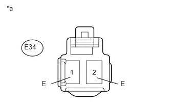
0.492,0.872 0.787,1.024 0.295,0.151 10 E34 0.137,0.088 0.307,0.262 0.170,0.174 10 *a 0.847,1.629 0.966,1.780 0.119,0.151 10 E 2.452,1.629 2.570,1.780 0.119,0.151 10 E 1.432,1.577 1.037,1.715 false 1.97,1.589 2.406,1.72 false

Disconnect the E34 quick heater assembly connector.


b.

Measure the resistance according to the value(s) in the table below.

Standard Resistance:
Tester Connection Condition Specified Condition
E34-1 (E) - Body ground Always Below 1 Ω
E34-2 (E) - Body ground


Text in Illustration
*a Front view of wire harness connector
(to Quick Heater Assembly)


OK

6.INSPECT QUICK HEATER ASSEMBLY

NG

REPAIR OR REPLACE HARNESS OR CONNECTOR

6.INSPECT QUICK HEATER ASSEMBLY
a.
E140255E08
1.947,3.878 2.622,4.138 false 2.633,4.092 2.789,4.273 0.156,0.181 10 E 1.569,3.878 0.895,4.138 false 0.684,4.092 0.840,4.273 0.156,0.181 10 E 2.069,1.597 2.626,1.912 false 2.638,1.865 2.794,2.046 0.156,0.181 10 B 1.52,1.602 0.9,1.912 false 1.786,1.657 1.796,2.157 false 0.729,1.865 0.885,2.046 0.156,0.181 10 B 1.739,2.181 1.895,2.362 0.156,0.181 10 B

Remove the quick heater assembly (See page Vehicle Interior>HEATING / AIR CONDITIONING>PTC HEATER ASSEMBLY>REMOVAL).


b.

Measure the resistance according to the value(s) in the table below.

Standard Resistance:
Tester Connection Condition Specified Condition
1 (B) - 1 (E) Always Below 1 kΩ
2 (B) - 1 (E)
2 (B) - 2 (E)
3 (B) - 2 (E)


OK

7.CHECK AIR CONDITIONING AMPLIFIER ASSEMBLY

NG

7.CHECK AIR CONDITIONING AMPLIFIER ASSEMBLY
a.
U166100E01
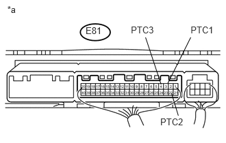
1.302,0.384 1.587,0.544 0.286,0.161 10 E81 0.111,0.059 0.383,0.219 0.272,0.161 10 *a 2.899,0.377 3.281,0.537 0.383,0.161 10 PTC1 2.438,1.78 2.857,1.941 0.420,0.161 10 PTC2 1.991,0.377 2.410,0.537 0.420,0.161 10 PTC3 2.551,1.276 2.901,0.571 false 2.45,1.291 2.213,0.571 false 2.608,1.425 2.712,1.769 false

Remove the air conditioning amplifier assembly with its connectors still connected (See page Vehicle Interior>HEATING / AIR CONDITIONING>AIR CONDITIONING AMPLIFIER>REMOVAL).


b.

Measure the voltage according to the value(s) in the table below.

Standard Voltage:
Tester Connection Condition Specified Condition
E81-3 (PTC1) - Body ground Engine idling
Set temperature MAX. HOT
Engine coolant temperature below 65°C (149°F)
Ambient temperature below 10°C (50°F)
Blower switch off → LO level
Below 1 V → 11 to 14 V*
E81-22 (PTC2) - Body ground
E81-4 (PTC3) - Body ground


Text in Illustration
*a Component with harness connected
(Air Conditioning Amplifier Assembly)

HINT:

*: After the measurement conditions are met, wait 30 seconds before performing measurements.


OK

NG

REPLACE AIR CONDITIONING AMPLIFIER ASSEMBLY