INTERIOR PANELS / TRIM ROOF HEADLINING(w/o Sliding Roof) INSTALLATION
CAUTION / NOTICE / HINT
- HINT:
- ·
Use the same procedure for RHD and LHD vehicles.
·The procedure listed below is for LHD vehicles.
·A bolt without a torque specification is shown in the standard bolt chart (See page General>SPECIFICATIONS>STANDARD BOLT>SPECIFIED TORQUE FOR STANDARD BOLTS).
PROCEDURE

 62597A
1.INSTALL SIDE TRIM BOX
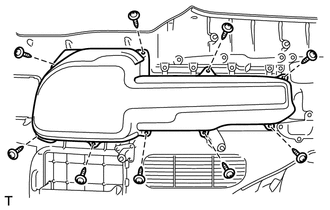
Install the side trim box with the 9 screws.
62598D
2.INSTALL SIDE TRIM BOX COVER
Install the side trim box cover.
62605Q
3.INSTALL QUARTER TRIM LID SUB-ASSEMBLY RH
Install the quarter trim lid sub-assembly RH.
62522A
4.INSTALL QUARTER TRIM COVER LH (w/o Rear No. 2 Seat or w/ Rear No. 2 Seat, for Face to Face Seat Type)
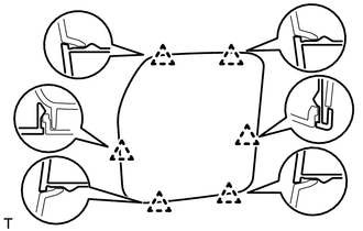
Attach the 6 clips to install the quarter trim cover LH.
62521B
5.INSTALL QUARTER TRIM COVER RH (w/o Rear No. 2 Seat or w/ Rear No. 2 Seat, for Face to Face Seat Type)
- HINT:
-
Use the same procedures described for the LH side.
71866B
6.INSTALL REAR NO. 2 SEAT COVER BEZEL (w/ Rear No. 2 Seat, except Face to Face Seat Type)
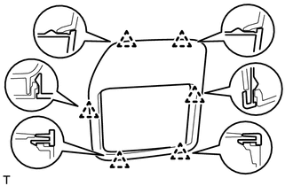
Attach the 6 clips to install the rear No. 2 seat cover bezel.
71865A
7.INSTALL REAR NO. 1 SEAT COVER BEZEL (w/ Rear No. 2 Seat, except Face to Face Seat Type)
- HINT:
-
Use the same procedures described for the rear No. 2 seat cover bezel.
72058C
8.INSTALL REAR SEAT LOCK CONTROL LEVER SUB-ASSEMBLY LH (w/ Rear No. 2 Seat, except Face to Face Seat Type)
72057A
9.INSTALL REAR SEAT LOCK CONTROL LEVER SUB-ASSEMBLY RH (w/ Rear No. 2 Seat, except Face to Face Seat Type)
- HINT:
-
Use the same procedures described for the LH side.
62526D
10.INSTALL NO. 2 SIDE TRIM BASE COVER LH (w/ Rear Heater)
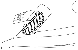
Attach the 4 claws to install the No. 2 side trim base cover LH.
62516B
11.INSTALL NO. 2 SIDE TRIM BASE COVER RH (w/ Rear Heater)
- HINT:
-
Use the same procedures described for the LH side.
62525D
12.INSTALL NO. 1 SIDE TRIM BASE COVER LH (w/ Rear Heater)
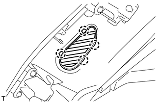
Attach the 4 claws to install the No. 1 side trim base cover LH.
62515B
13.INSTALL NO. 1 SIDE TRIM BASE COVER RH (w/ Rear Heater)
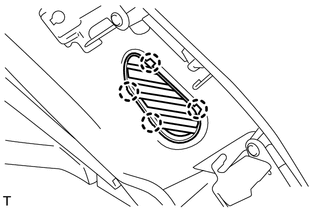
Attach the 4 claws to install the No. 1 side trim base cover RH.
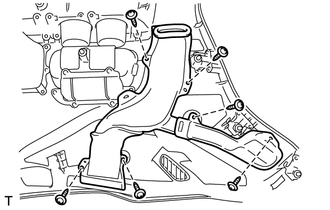
Install the duct with the 6 screws.
64932B
14.INSTALL TONNEAU COVER HANGER LH (w/ Tonneau Cover)
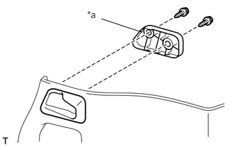
Install the tonneau cover hanger LH and rear quarter trim base with the 2 screws.
| *a | Rear Quarter Trim Base |
64931B
15.INSTALL TONNEAU COVER HANGER RH (w/ Tonneau Cover)
- HINT:
-
Use the same procedures described for the LH side.
64934A
16.INSTALL TONNEAU COVER HOLDER BRACKET LH (w/ Tonneau Cover)
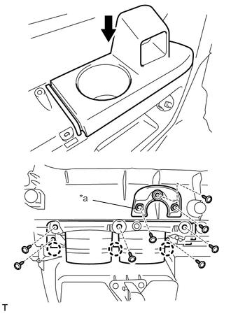
Attach the 3 claws to install the tonneau cover holder bracket LH.
Install the front quarter trim base with the 3 screws and then install the remaining 5 screws.
| *a | Front Quarter Trim Base |
64933A
17.INSTALL TONNEAU COVER HOLDER BRACKET RH (w/ Tonneau Cover)
- HINT:
-
Use the same procedures described for the LH side.
66992
18.INSTALL NO. 2 CUP HOLDER
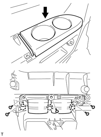
Attach the 3 claws to install the No. 2 cup holder.
Install the 5 screws.
66991B
19.INSTALL NO. 1 CUP HOLDER
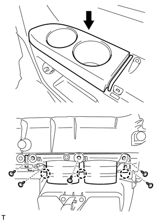
Attach the 3 claws to install the No. 1 cup holder.
Install the 5 screws.
62502B
20.INSTALL QUARTER TRIM COVER SUB-ASSEMBLY LH
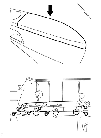
Attach the 4 claws to install the quarter trim cover sub-assembly LH.
Install the 7 screws.
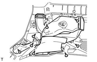
w/ Rear Heater:
Install the duct with the 8 screws.
62501C
21.INSTALL QUARTER TRIM COVER SUB-ASSEMBLY RH
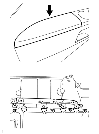
Attach the 4 claws to install the quarter trim cover sub-assembly RH.
Install the 7 screws.
73372C
22.INSTALL REAR NO. 2 SEAT SHOULDER BELT HANGER LH
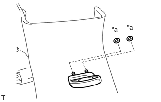
Install the rear No. 2 seat shoulder belt hanger LH with new 2 spring nuts.
| *a | Spring Nut |
73371C
23.INSTALL REAR NO. 2 SEAT SHOULDER BELT HANGER RH
- HINT:
-
Use the same procedures described for the LH side.
73371A
24.INSTALL REAR SEAT SHOULDER BELT HANGER (w/ Rear No. 2 Seat, except Face to Face Seat Type)
- HINT:
-
Use the same procedure for both rear No. 1 seat shoulder belt hangers.
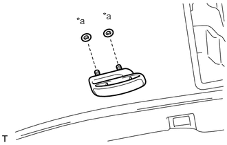
Install the rear No. 1 seat shoulder belt hanger with new 2 spring nuts.
| *a | Spring Nut |
62488A
25.INSTALL ROOF SIDE INNER GARNISH COVER LH (w/ Rear No. 2 Seat, except Face to Face Seat Type)
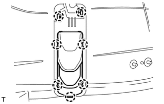
Attach the 7 claws to install the roof side inner garnish cover LH.
62487A
26.INSTALL ROOF SIDE INNER GARNISH COVER RH (w/ Rear No. 2 Seat, except Face to Face Seat Type)
- HINT:
-
Use the same procedures described for the LH side.
73034
27.INSTALL REAR SHOULDER BELT ANCHOR PLATE SUB-ASSEMBLY LH
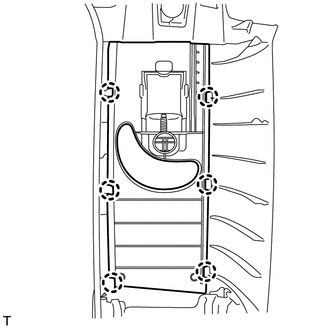
Attach the 6 claws to install the rear shoulder belt anchor plate sub-assembly LH.
73033
28.INSTALL REAR SHOULDER BELT ANCHOR PLATE SUB-ASSEMBLY RH
- HINT:
-
Use the same procedures described for the LH side.
73024
29.INSTALL FRONT SHOULDER BELT ANCHOR PLATE SUB-ASSEMBLY LH
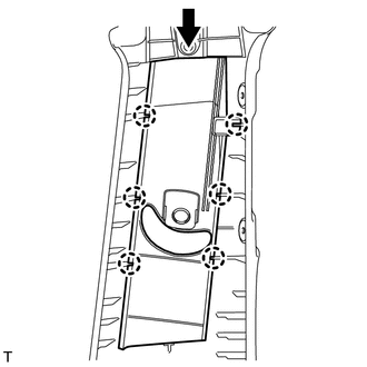
Slide the front shoulder belt anchor plate sub-assembly LH in the direction shown in the illustration and attach the 6 claws to install the front shoulder belt anchor plate sub-assembly LH.
73023
30.INSTALL FRONT SHOULDER BELT ANCHOR PLATE SUB-ASSEMBLY RH
- HINT:
-
Use the same procedures described for the LH side.
67916
31.INSTALL REAR DOOR SCUFF PLATE OUTSIDE LH
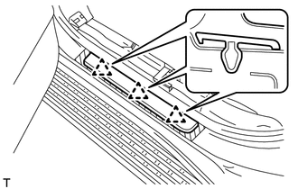
Attach the 3 clips to install the rear door scuff plate outside LH.
67915
32.INSTALL REAR DOOR SCUFF PLATE OUTSIDE RH
- HINT:
-
Use the same procedures described for the LH side.
67912A
33.INSTALL FRONT DOOR SCUFF PLATE OUTSIDE LH
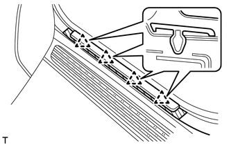
Attach the 4 clips to install the front door scuff plate outside LH.
67911B
34.INSTALL FRONT DOOR SCUFF PLATE RH
- HINT:
-
Use the same procedures described for the LH side.
67881A
35.INSTALL BACK DOOR WEATHERSTRIP
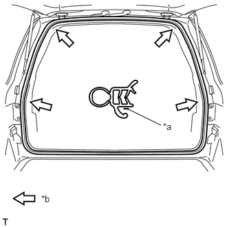
Install the back door weatherstrip as shown in the illustration.
| *a | Alignment Mark |
| *b | Mark |
62332A
36.INSTALL REAR DOOR OPENING TRIM WEATHERSTRIP LH
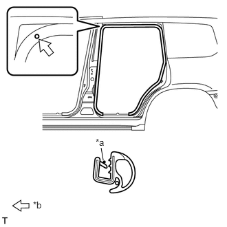
Install the rear door opening trim weatherstrip LH as shown in the illustration.
| *a | Alignment Mark |
| *b | Mark |
62331A
37.INSTALL REAR DOOR OPENING TRIM WEATHERSTRIP RH
- HINT:
-
Use the same procedures described for the LH side.
62312B
38.INSTALL FRONT DOOR OPENING TRIM WEATHERSTRIP LH
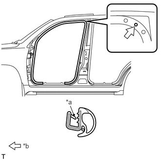
Install the front door opening trim weatherstrip LH as shown in the illustration.
| *a | Alignment Mark |
| *b | Mark |
62311B
39.INSTALL FRONT DOOR OPENING TRIM WEATHERSTRIP RH
- HINT:
-
Use the same procedures described for the LH side.
63310
40.INSTALL ROOF HEADLINING ASSEMBLY
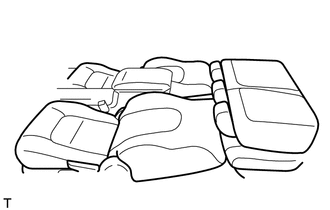
- HINT:
- ·
for Manual Seat:
When installing the roof headlining assembly, move the front seat and rear No. 1 seat to the position shown in the illustration.
·for Power Seat:
When installing the roof headlining assembly, connect the cable to the negative (-) battery terminal and move the front seat and No. 1 rear seat to the position shown in the illustration.
·for Power Seat:
After moving the seats, disconnect the cable from the negative (-) battery terminal.
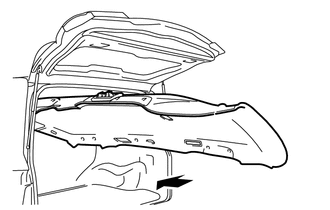
Place the roof headlining assembly in the cabin from the rear of the vehicle as shown in the illustration.
- NOTICE:
-
Be careful not to damage the roof headlining assembly when placing it in the cabin.
for 3 Person Seat Type Rear No. 2 Seat:
Attach the 2 guides, 12 claws and 2 clips to install the headlining.
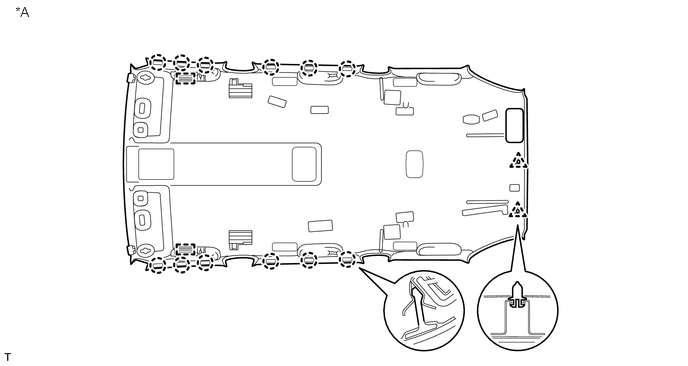
| *A | for 3 Person Seat Type Rear No. 2 Seat | - | - |
except 3 Person Seat Type Rear No. 2 Seat:
Attach the 2 guides, 12 claws and 3 clips to install the headlining.
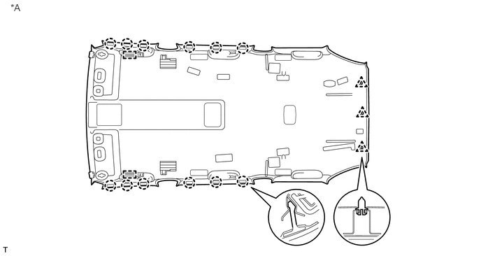
| *A | except 3 Person Seat Type Rear No. 2 Seat | - | - |
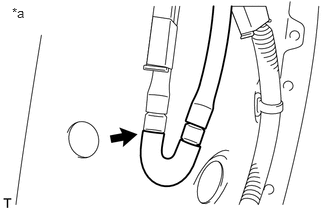
w/ Rear Wiper:
Connect the washer hose.
| *a | Rear Left Side |
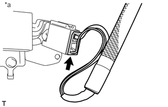
Connect the antenna cord connector.
| *a | Rear Right Side |
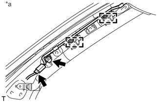
Connect the antenna cord connector and attach the 2 clamps.
Install the bolt.
| *a | Front Right Side |
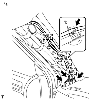
Connect the 3 roof wire connectors and 4 clamps.
w/ Rear Wiper:
Connect the washer hose.
| *a | Front Left Side |
| *b | Washer Hose |
w/ Pre-crash Safety System:
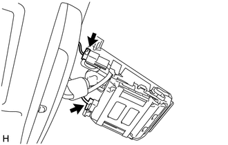
w/o Camera Heater:
Connect the 2 connectors.
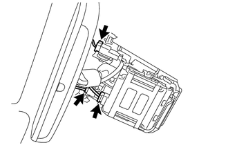
w/ Camera Heater:
Connect the 3 connectors.
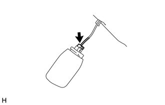
w/ Rain Sensor:
Connect the connector.
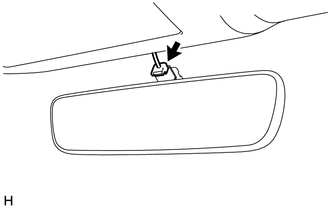
w/ EC Mirror:
Connect the connector.
62432C
41.INSTALL FRONT ROOF SIDE RAIL GARNISH LH
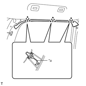
Install 3 new clips to the front roof side rail garnish LH.
| *a | New Clip |
Attach the 3 clips to install the front roof side rail garnish LH.
62431C
42.INSTALL FRONT ROOF SIDE RAIL GARNISH RH
- HINT:
-
Use the same procedures described for the LH side.
74630B
43.INSTALL 3RD SEAT ASSIST GRIP ASSEMBLY (w/ Rear No. 2 Seat, except Face to Face Seat Type)
- HINT:
-
Use the same procedure for both 3rd seat assist grip assemblies.
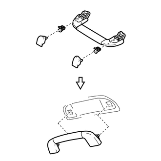
Assemble the assist grip, 2 clips and 2 covers as shown in the illustration.
Install the 3rd seat assist grip assembly.
74610K
44.INSTALL NO. 2 ASSIST GRIP ASSEMBLY LH
w/ Rear No. 2 Seat, except Face to Face Seat Type or w/o Rear No. 2 Seat:
Install the No. 2 assist grip assembly.
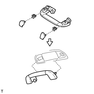
Assemble the assist grip, 2 clips and 2 covers as shown in the illustration.
Install the No. 2 assist grip assembly LH.
w/ Rear No. 2 Seat, for Face to Face Seat Type:
Install the No. 2 assist grip assembly.
Assemble the assist grip, 2 clips and 2 covers as shown in the illustration.
Install the No. 2 assist grip assembly LH.
74610B
45.INSTALL NO. 2 ASSIST GRIP ASSEMBLY RH
- HINT:
-
Use the same procedures described for the LH side.
74610U
46.INSTALL ASSIST GRIP ASSEMBLY
- HINT:
-
Use the same procedure for both assist grip assemblies.
Assemble the assist grip, 2 clips and 2 covers as shown in the illustration.
Install the assist grip assembly.
73139B
47.INSTALL SEAT BELT ANCHOR COVER (for 3 Person Seat Type Rear No. 2 Seat)
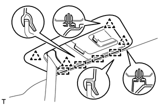
Attach the 4 guides and 4 clips to install the seat belt anchor cover.
86466D
48.INSTALL NO. 1 FORWARD RECOGNITION COVER (w/ Pre-crash Safety System)
86466E
49.INSTALL NO. 2 FORWARD RECOGNITION COVER (w/ Pre-crash Safety System)
89943
50.INSTALL RAIN SENSOR COVER (w/ Rain Sensor)
87834
51.INSTALL INNER REAR VIEW MIRROR STAY HOLDER COVER (w/ EC Mirror)
74330C
52.INSTALL CENTER VISOR ASSEMBLY LH (w/ Sub Visor)
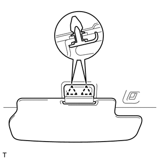
Attach the 2 clips to install the center visor assembly LH.
74330B
53.INSTALL CENTER VISOR ASSEMBLY RH (w/ Sub Visor)
- HINT:
-
Use the same procedures described for the LH side.
74348
54.INSTALL VISOR HOLDER
- HINT:
-
Use the same procedure for visor holders.
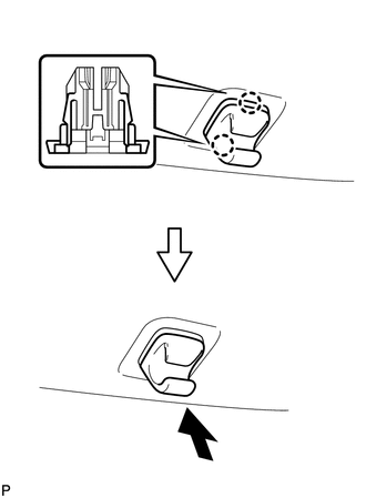
Attach the 2 claws.
Push the visor holder in to install it.
74320
55.INSTALL VISOR ASSEMBLY LH
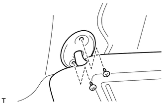
Install the visor assembly LH with the 2 screws.
74310
56.INSTALL VISOR ASSEMBLY RH
- HINT:
-
Use the same procedures described for the LH side.
74325
57.INSTALL VISOR BRACKET COVER
- HINT:
-
Use the same procedure for visor bracket covers.
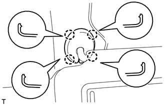
Attach the 4 claws to install the visor bracket cover.
81290
58.INSTALL NO. 3 ROOM LIGHT ASSEMBLY
81240
59.INSTALL NO. 1 ROOM LIGHT ASSEMBLY
for Bulb Type:
(See page Vehicle Interior>LIGHTING (INT)>ROOM LIGHT(for Center)>INSTALLATION)
for LED Type:
(See page Vehicle Interior>LIGHTING (INT)>ROOM LIGHT(for Center)>INSTALLATION)
81260A
60.INSTALL MAP LIGHT ASSEMBLY (w/ Map Light)
62472D
61.INSTALL REAR UPPER PILLAR GARNISH LH
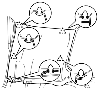
Attach the 5 clips to install the rear upper pillar garnish LH.
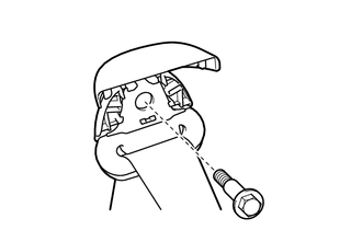
w/ Rear No. 2 Seat, except Face to Face Seat Type:
Install the seat belt shoulder anchor with the bolt.
- Torque:
- 42 N*m (428 kgf*cm, 31 ft.*lbf)
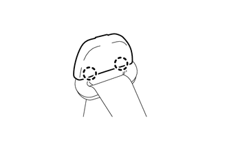
Attach the 2 claws to close the seat belt shoulder anchor cover.
62471D
62.INSTALL REAR UPPER PILLAR GARNISH RH
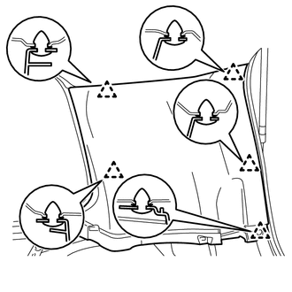
w/o Power Back Door:
Attach the 5 clips to install the rear upper pillar garnish RH.
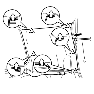
w/ Power Back Door:
Pass the power back door rod through the rear upper pillar garnish RH.
| *a | Power Back Door Rod |
Attach the 5 clips to install the rear upper pillar garnish RH.
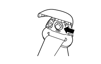
Install the seat belt shoulder anchor with the bolt.
- Torque:
- 42 N*m (428 kgf*cm, 31 ft.*lbf)
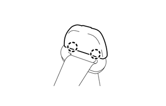
Attach the 2 claws to close the seat belt shoulder anchor cover.
67847
63.INSTALL BACK DOOR SERVICE HOLE COVER RH (w/ Power Back Door)
67937B
64.INSTALL BACK DOOR SIDE GARNISH RH (w/ Power Back Door)
67939B
65.INSTALL CENTER BACK DOOR GARNISH (w/ Power Back Door)
62639
66.INSTALL REAR FRONT QUARTER TRIM GARNISH LH
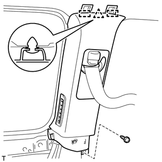
Pass the seat belt anchor through the rear front quarter trim garnish LH.
Attach the clip and 2 guides to install the rear front quarter trim garnish LH.
Install the screw.
62638
67.INSTALL REAR FRONT QUARTER TRIM GARNISH RH
- HINT:
-
Use the same procedures described for the LH side.
62520P
68.INSTALL FRONT QUARTER TRIM PANEL ASSEMBLY LH
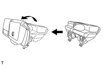
- HINT:
-
When installing the front quarter trim panel assembly LH, operate the reclining adjuster release handle and move the No. 1 rear seat to the position shown in the illustration.
w/ Rear No. 2 Seat, except Face to Face Seat Type:
w/o Rear Air Conditioning System:
Connect the rear seat lock control lever cable.
w/ Rear Air Conditioning System:
Connect the thermistor connector and rear seat lock control lever cable.
Attach the 18 clips and 2 claws to install the front quarter trim panel assembly LH.
Install the clip and bolt.
- Torque:
- 12 N*m (122 kgf*cm, 9 ft.*lbf)
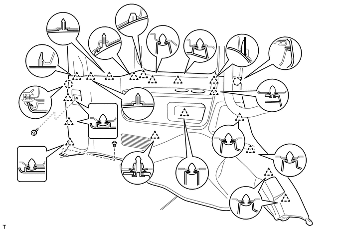
w/o Rear No. 2 Seat or w/ Rear No. 2 Seat, for Face to Face Seat Type:
Attach the 18 clips and 2 claws to install the front quarter trim panel assembly LH.
Install the clip.
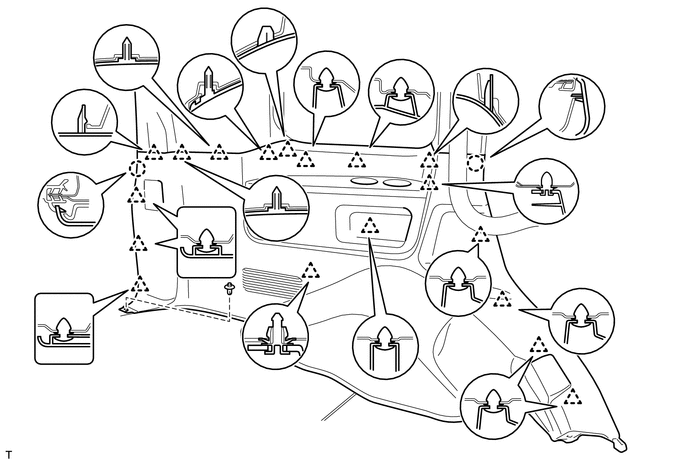
w/ Tonneau Cover:
Attach the 18 clips and 2 claws to install the front quarter trim panel assembly LH.
Install the screw and clip.
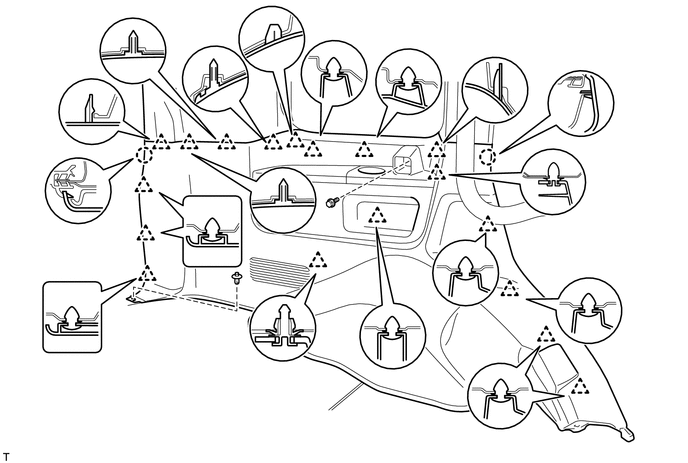
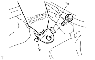
w/ Rear No. 2 Seat, except Face to Face Seat Type:
Install the rear No. 2 seat belt anchor with the bolt.
- Torque:
- 42 N*m (428 kgf*cm, 31 ft.*lbf)
- NOTICE:
-
Do not overlap the anchor part of the seat belt and protruding parts of the vehicle body.
| *a | Protruding Part |
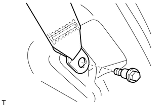
Install the rear No. 1 seat belt anchor with the bolt.
- Torque:
- 42 N*m (428 kgf*cm, 31 ft.*lbf)
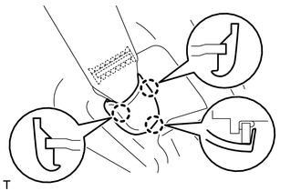
Attach the 3 claws to install the outer lap belt anchor cover.
62510P
69.INSTALL FRONT QUARTER TRIM PANEL ASSEMBLY RH
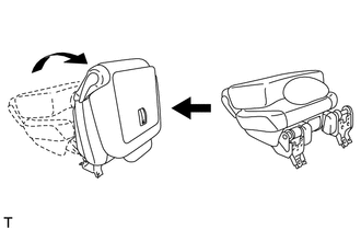
- HINT:
-
When installing the front quarter trim panel assembly RH, operate the reclining adjuster release handle and move the No. 1 rear seat to the position shown in the illustration.
w/ Rear No. 2 Seat, except Face to Face Seat Type:
w/o Rear Air Conditioning System:
Connect the rear seat lock control lever cable.
w/ Rear Air Conditioning System:
Connect the thermistor connector and rear seat lock control lever cable.
Attach the 16 clips and 2 claws to install the front quarter trim panel assembly RH.
Install the clip and bolt.
- Torque:
- 12 N*m (122 kgf*cm, 9 ft.*lbf)
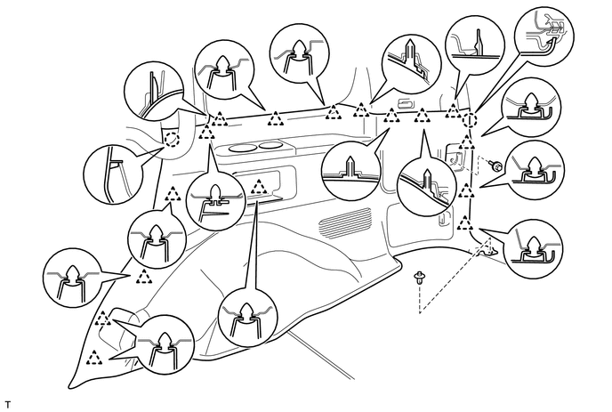
w/o Rear No. 2 Seat or w/ Rear No. 2 Seat, for Face to Face Seat Type:
Attach the 16 clips and 2 claws to install the front quarter trim panel assembly RH.
Install the clip.
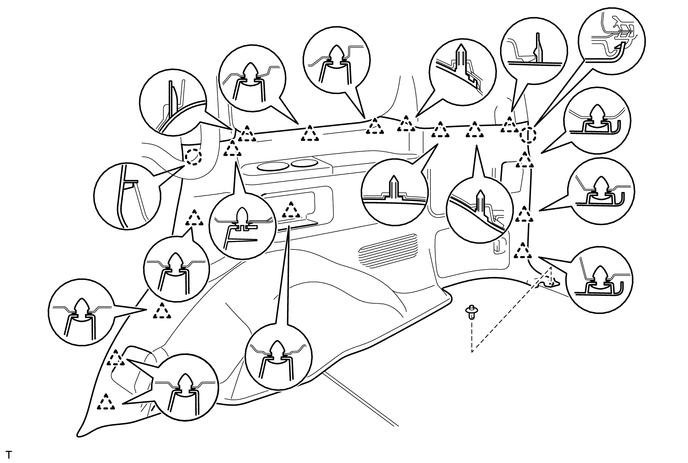
w/ Tonneau Cover:
Attach the 16 clips and 2 claws to install the front quarter trim panel assembly RH.
Install the screw and clip.
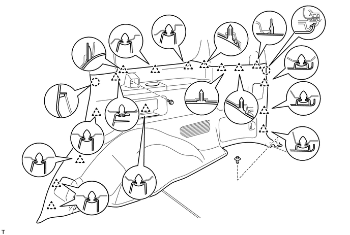
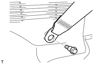
w/ Rear No. 2 Seat, except Face to Face Seat Type:
Install the rear No. 2 seat belt anchor with the bolt.
- Torque:
- 42 N*m (428 kgf*cm, 31 ft.*lbf)
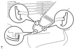
Attach the 3 claws to install the outer lap belt anchor cover.
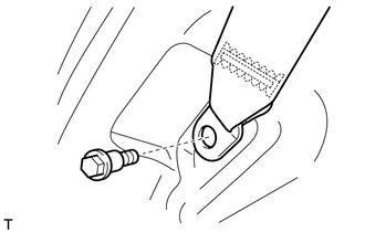
Install the rear No. 1 seat belt anchor with the bolt.
- Torque:
- 42 N*m (428 kgf*cm, 31 ft.*lbf)
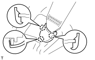
Attach the 3 claws to install the outer lap belt anchor cover.
71845B
70.INSTALL REAR SEAT COVER CAP (w/ Rear No. 2 Seat, except Face to Face Seat Type)
- HINT:
-
Use the same procedure to install the rear seat cover cap on the other side.
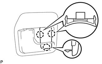
Attach the 3 claws to install the rear seat cover cap.
64937A
71.INSTALL NO. 1 TONNEAU COVER HOLDER CAP (w/ Tonneau Cover)
- HINT:
-
Use the same procedure for No. 1 tonneau cover holder caps.
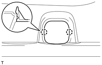
Attach the 2 claws to install the No. 1 tonneau cover holder cap.
62412
72.INSTALL CENTER PILLAR GARNISH LH
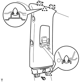
Pass the seat belt anchor through the center pillar garnish LH.
Attach the 2 clips and 2 guides to install the center pillar garnish LH.
Install the bolt.
62411
73.INSTALL CENTER PILLAR GARNISH RH
- HINT:
-
Use the same procedures described for the LH side.
74620A
74.INSTALL REAR ASSIST GRIP ASSEMBLY
- HINT:
-
Use the same procedure for both rear assist grip assemblies.
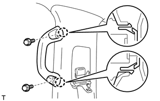
Attach the 2 claws to install the rear assist grip assembly.
Install the 2 bolts.
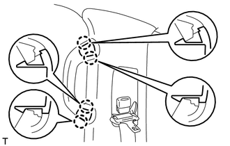
Attach the 4 claws to install the 2 assist grip plugs.
62414A
75.INSTALL CENTER LOWER PILLAR GARNISH LH
- HINT:
- ·
for Manual Seat:
When installing the center lower pillar garnish LH, move the front seat and seatback to the foremost upright position.
·for Power Seat:
When installing the center lower pillar garnish LH, connect the cable to the negative (-) battery terminal and operate the power seat switch to move the front seat and seatback to the foremost upright position.
·for Power Seat:
After moving the front seat, disconnect the cable from the negative (-) battery terminal.
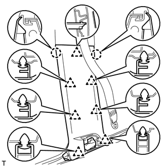
Attach the 2 claws and 7 clips to install the center lower pillar garnish LH.
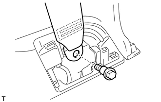
Install the seat belt anchor with the bolt.
- Torque:
- 42 N*m (428 kgf*cm, 31 ft.*lbf)
62413A
76.INSTALL CENTER LOWER PILLAR GARNISH RH
- HINT:
-
Use the same procedures described for the LH side.
62422
77.INSTALL CENTER PILLAR GARNISH COVER LH
- HINT:
- ·
for Manual Seat:
When installing the center pillar garnish cover LH, move the front seat and seatback to the foremost upright position.
·for Power Seat:
When installing the center pillar garnish cover LH, connect the cable to the negative (-) battery terminal and operate the power seat switch to move the front seat and seatback to the foremost upright position.
·for Power Seat:
After moving the front seat, disconnect the cable from the negative (-) battery terminal.
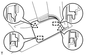
Attach the 2 clips and 2 guides to install the center pillar garnish cover LH.
62421
78.INSTALL CENTER PILLAR GARNISH COVER RH
- HINT:
-
Use the same procedures described for the LH side.
62212
79.INSTALL FRONT PILLAR GARNISH LH
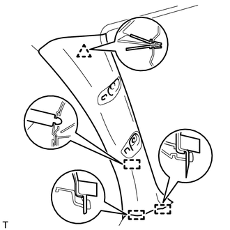
w/ Speaker:
Connect the speaker connector.
Attach the clip and 3 guides to install the front pillar garnish LH.
62211
80.INSTALL FRONT PILLAR GARNISH RH
- HINT:
-
Use the same procedures described for the LH side.
74610A
81.INSTALL ASSIST GRIP SUB-ASSEMBLY
- HINT:
-
Use the same procedure for both assist grip sub-assemblies.
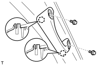
Attach the 2 claws to install the assist grip sub-assembly.
Install the 2 bolts.
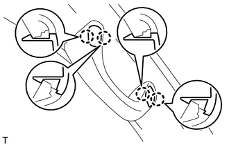
Attach the 4 claws to install the 2 assist grip plugs.
58574A
82.INSTALL REAR FLOOR MAT REAR SUPPORT PLATE
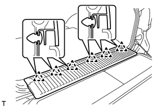
Attach the 6 clips to install the rear floor mat support plate.
67918E
83.INSTALL REAR DOOR SCUFF PLATE LH
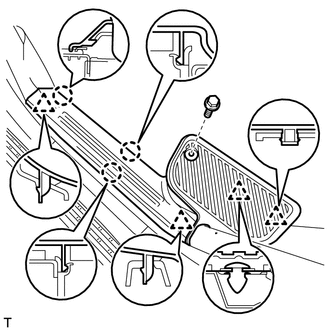
Attach the 3 claws and 4 clips to install the rear door scuff plate LH.
Install the screw.
67917C
84.INSTALL REAR DOOR SCUFF PLATE RH
- HINT:
-
Use the same procedures described for the LH side.
51775
85.INSTALL REAR STEP COVER
- HINT:
-
Use the same procedure for both rear step covers.
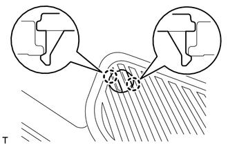
Attach the 2 claws to install the rear step cover.
67914B
86.INSTALL FRONT DOOR SCUFF PLATE LH
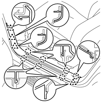
Attach the 7 claws and 4 clips to install the front door scuff plate LH.
67913B
87.INSTALL FRONT DOOR SCUFF PLATE RH
- HINT:
-
Use the same procedures described for the LH side.
88.INSTALL REAR NO. 2 SEAT ASSEMBLY LH (except Face to Face Seat Type)
89.INSTALL REAR NO. 2 SEAT ASSEMBLY RH (except Face to Face Seat Type)
- HINT:
-
Use the same procedures described for the LH side.
90.INSTALL REAR NO. 2 SEAT ASSEMBLY LH (for Face to Face Seat Type)
91.INSTALL REAR NO. 2 SEAT ASSEMBLY RH (for Face to Face Seat Type)
- HINT:
-
Use the same procedures described for the LH side.
64910J
92.INSTALL TONNEAU COVER ASSEMBLY (w/ Tonneau Cover)
Install the tonneau cover assembly.
93.CONNECT CABLE TO NEGATIVE BATTERY TERMINAL
- NOTICE:
-
When disconnecting the cable, some systems need to be initialized after the cable is reconnected (See page General>INTRODUCTION>REPAIR INSTRUCTION>INITIALIZATION).
94.CHECK SRS WARNING LIGHT