Home › Vehicle Interior › INTERIOR PANELS / TRIM › ROOF HEADLINING (w/ Sliding Roof) › from 2015.08
RM2660E _58 Vehicle Interior _052849 INTERIOR PANELS / TRIM _0255720 ROOF HEADLINING(w/ Sliding Roof) A

INTERIOR PANELS / TRIM  ROOF HEADLINING(w/ Sliding Roof)  REASSEMBLY  


CAUTION / NOTICE / HINT

HINT:
·

Use the same procedure for RHD and LHD vehicles.

·

The procedure listed below is for LHD vehicles.


PROCEDURE

Hide 82171 2.INSTALL NO. 1 ROOF WIRE

a.

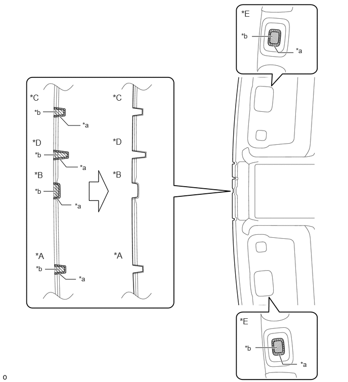
When using a new roof headlining:

i.

Using a knife, cut the roof headlining at the markings as shown in the illustration.

HINT:

Make sure to cut the roof headlining at the same positions as the removed roof headlining.

B605454N01
0.885,2.302 1.177,2.302 true 5.188,0.75 5.604,0.75 true 6.042,1.083 5.729,1.083 5.729,1.083 5.635,0.927 true 1.563,5.75 1.354,5.75 1.354,5.75 1.219,5.635 true 1.229,3.271 1.365,3.438 1.365,3.438 1.604,3.438 true 1.219,2.385 1.406,2.583 1.406,2.583 1.656,2.583 true 1.177,4.083 1.271,4.219 1.271,4.219 1.469,4.219 true 0.927,5.542 1.188,5.542 true 0.896,3.938 1.146,3.938 true 0.906,3.188 1.188,3.188 true 5.26,7.156 5.708,7.156 true 5.75,7.292 5.823,7.5 5.823,7.5 6.115,7.5 true 0.729,5.167 1.104,5.406 0.375,0.24 12 false *A 2.323,3.49 2.698,3.729 0.375,0.24 12 false *B 2.323,1.906 2.698,2.146 0.375,0.24 12 false *C 2.323,2.813 2.698,3.052 0.375,0.24 12 false *D 4.969,0.177 5.344,0.417 0.375,0.24 12 false *E 1.698,2.49 2.042,2.719 0.344,0.229 10 false *a 0.719,3.104 1.031,3.302 0.313,0.198 10 false *b 0.708,2.229 1.021,2.427 0.313,0.198 10 false *b 5.042,7.083 5.354,7.281 0.313,0.198 10 false *b 0.719,3.854 1.063,4.083 0.344,0.229 10 false *b 1.646,3.365 1.958,3.563 0.313,0.198 10 false *a 1.542,4.156 1.854,4.354 0.313,0.198 10 false *a 1.625,5.656 1.938,5.854 0.313,0.198 10 false *a 0.708,3.5 1.083,3.74 0.375,0.24 12 false *B 0.667,2.833 1.042,3.073 0.375,0.24 12 false *D 0.615,1.906 0.99,2.146 0.375,0.24 12 false *C 2.344,5.156 2.719,5.396 0.375,0.24 12 false *A 4.938,6.51 5.313,6.75 0.375,0.24 12 false *E 4.969,0.656 5.281,0.854 0.313,0.198 10 false *b 6.094,0.958 6.438,1.188 0.344,0.229 10 false *a 6.188,7.417 6.5,7.615 0.313,0.198 10 false *a 0.74,5.448 1.083,5.677 0.344,0.229 10 false *b

Text in Illustration
*A for RHD with Rain Sensor *B w/ EC Mirror
*C for LHD with Rain Sensor *D w/ Pre-crash Safety System
*E w/ Sub Visor - -
*a Marking *b Cut Area


b.

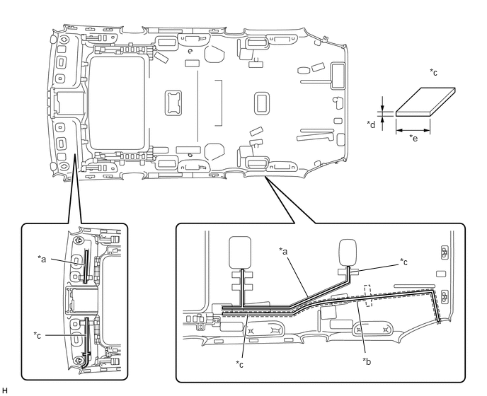
Place double-sided tape along the center of the harness marking and washer marking.

HINT:

Make sure that the double-sided tape is not peeling off or misaligned.

U155973E03
1.271,4.938 0.667,4.938 true 1.25,3.906 0.75,3.813 true 3.646,4.625 3.563,5.271 true 5.25,4.417 5.375,5.198 true 5.156,4.01 5.865,3.896 true 4.531,4.375 4.229,3.792 false 0.552,3.729 0.74,3.906 0.188,0.177 10 false *a 5.333,5.24 5.521,5.417 0.188,0.177 10 false *b 3.469,5.281 3.656,5.458 0.188,0.177 10 false *c 6.323,0.979 6.51,1.156 0.188,0.177 10 false *c 4.104,3.615 4.292,3.792 0.188,0.177 10 false *a 5.885,3.771 6.073,3.948 0.188,0.177 10 false *c 0.49,4.854 0.677,5.031 0.188,0.177 10 false *c 5.396,1.75 5.583,1.927 0.188,0.177 10 false *d 6.021,1.948 6.208,2.125 0.188,0.177 10 false *e

Text in Illustration
*a Harness Marking *b Washer Marking
*c Double-sided Tape *d 1 mm (0.0394 in.)
*e 10 mm (0.394 in.) - -


c.

Remove the peeling paper from the double-sided tape while not touching the adhesive side.


d.

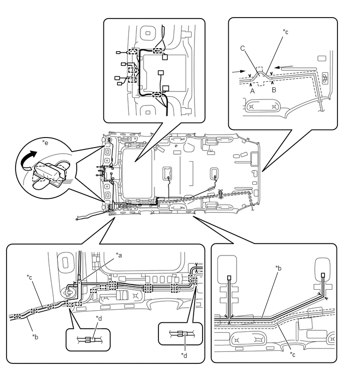
Align the triangle mark of the roof wire protector with the V mark of the headlining as shown in the illustration, and then attach the roof wire protector.


e.

Attach each clamp as shown in the illustration.


f.

Align the roof wire and washer hose with the V marks of the headlining as shown in the illustration, and attach them to the headlining.

HINT:
·

Attach the washer hose from the front to the point labeled A, and attach the washer hose from the rear to the point labeled B as shown in the illustration.

·

Attach the extra length of the washer hose to the part labeled C in the illustration.


g.

Turn the visor connectors approximately 90° clockwise to install them to the roof headlining.
B478234E01
5.521,1.552 5.875,0.76 false 5.396,1.583 5.083,1.052 false 0.552,6.563 0.677,6.875 false 0.885,6.385 0.667,5.833 false 1.667,5.844 2.365,5.365 true 1.917,7.042 2.031,6.688 true 3.844,6.917 3.844,7.281 true 5.438,6.594 5.771,5.646 true 5.75,6.698 6.042,7.25 true 4.99,0.917 5.146,1.115 0.156,0.198 10 false C 5.875,0.573 6.188,0.771 0.313,0.198 10 false *c 0.875,2.875 1.188,3.073 0.313,0.198 10 false *e 0.667,6.906 0.979,7.104 0.313,0.198 10 false *b 0.552,5.667 0.865,5.865 0.313,0.198 10 false *c 2.406,5.208 2.719,5.406 0.313,0.198 10 false *a 1.99,6.521 2.302,6.719 0.313,0.198 10 false *d 3.76,7.292 4.073,7.49 0.313,0.198 10 false *d 5.719,5.479 6.031,5.677 0.313,0.198 10 false *b 6.021,7.271 6.333,7.469 0.313,0.198 10 false *c 5.198,1.802 5.354,2 0.156,0.198 10 false A 5.646,1.781 5.802,1.979 0.156,0.198 10 false B

Text in Illustration
*a Protector *b No. 1 Roof Wire
*c Washer Hose *d Marking Tape
*e Visor Connector - -


h.

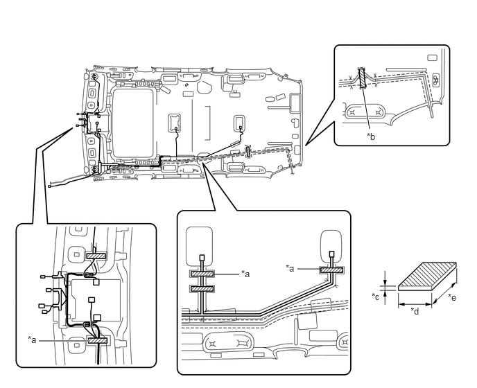
Place tape at the wire harness marking and washer marking locations as shown in the illustration to fix the roof wire and washer hose in place.

HINT:

Apply sufficient pressure when placing tape.

B478236E01
5.448,1.323 5.552,1.938 true 1.333,5.125 0.583,5.125 true 3.219,4.125 3.594,4.125 false 4.833,4.042 4.469,4.042 false 5.51,1.969 5.823,2.167 0.313,0.198 10 false *b 0.417,5.021 0.729,5.219 0.313,0.198 10 false *a 3.625,4.031 3.938,4.229 0.313,0.198 10 false *a 4.292,3.948 4.604,4.146 0.313,0.198 10 false *a 5.583,4.375 5.896,4.573 0.313,0.198 10 false *c 6.167,4.594 6.479,4.792 0.313,0.198 10 false *d 6.729,4.385 7.042,4.583 0.313,0.198 10 false *e

Text in Illustration
*a Harness Marking *b Washer Marking
*c 1 mm (0.0394 in.) *d 20 mm (0.787 in.)
*e 100 mm (3.94 in.) - -
V100155

Tape - -


Hide 63344 3.INSTALL NO. 4 ROOF SILENCER PAD
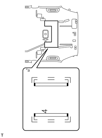
U155804E01
0.876,2.297 1.068,2.476 0.192,0.179 10 *a

a.

Align the silencer marking on the roof headlining with the No. 4 roof silencer pad and install the No. 4 roof silencer pad using double-sided tape as shown in the illustration.

Text in Illustration
*a Silencer Marking


Hide 63341 4.INSTALL NO. 1 ROOF SILENCER PAD
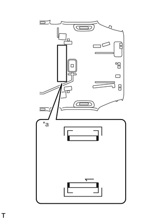
U155803E01
0.907,2.55 1.099,2.729 0.192,0.179 10 *a

a.

Align the silencer marking on the roof headlining with the No. 1 roof silencer pad and install the No. 1 roof silencer pad using double-sided tape as shown in the illustration.

Text in Illustration
*a Silencer Marking


Hide 88570D 5.INSTALL NO. 2 AIR OUTLET GRILLE ASSEMBLY (w/ Rear Air Conditioning System)

HINT:

Use the same procedure for both No. 2 air outlet grille assemblies.
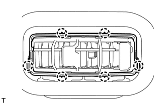

a.
B182435

Attach the 6 claws to install the No. 2 air outlet grille assembly.


Hide 88570B 6.INSTALL NO. 1 AIR OUTLET GRILLE ASSEMBLY (w/ Rear Air Conditioning System)

HINT:

Use the same procedures described for the No. 2 air outlet grille assembly.