AUDIO / VIDEO RADIO ANTENNA CORD INSTALLATION
PROCEDURE

 86101Q
1.INSTALL NO. 4 ANTENNA CORD SUB-ASSEMBLY
Attach each clamp to install the No. 4 antenna cord sub-assembly.
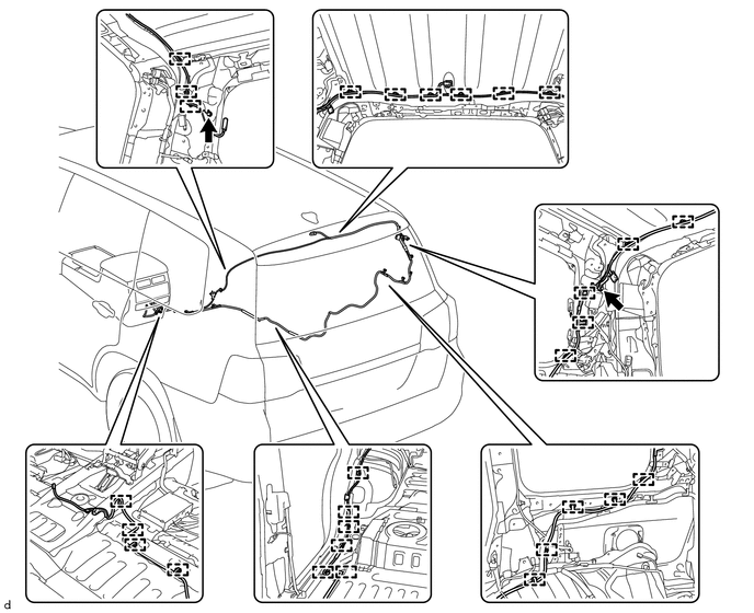
Install the 2 brackets with the 2 bolts.
- Torque:
- : 8.5 N*m (87 kgf*cm, 75 in.*lbf)
Connect each connector.
58510D
2.INSTALL FRONT FLOOR CARPET ASSEMBLY
Install the front floor carpet assembly (See page Audio / Visual / Telematics>AUDIO / VIDEO>STEREO COMPONENT AMPLIFIER>INSTALLATION).
86101J
3.INSTALL NO. 2 ANTENNA CORD SUB-ASSEMBLY
w/o Sliding Roof:
Apply new double-sided tape as shown in the illustration.
- HINT:
-
Attach double-sided tape to the hatched areas shown in the illustration below.
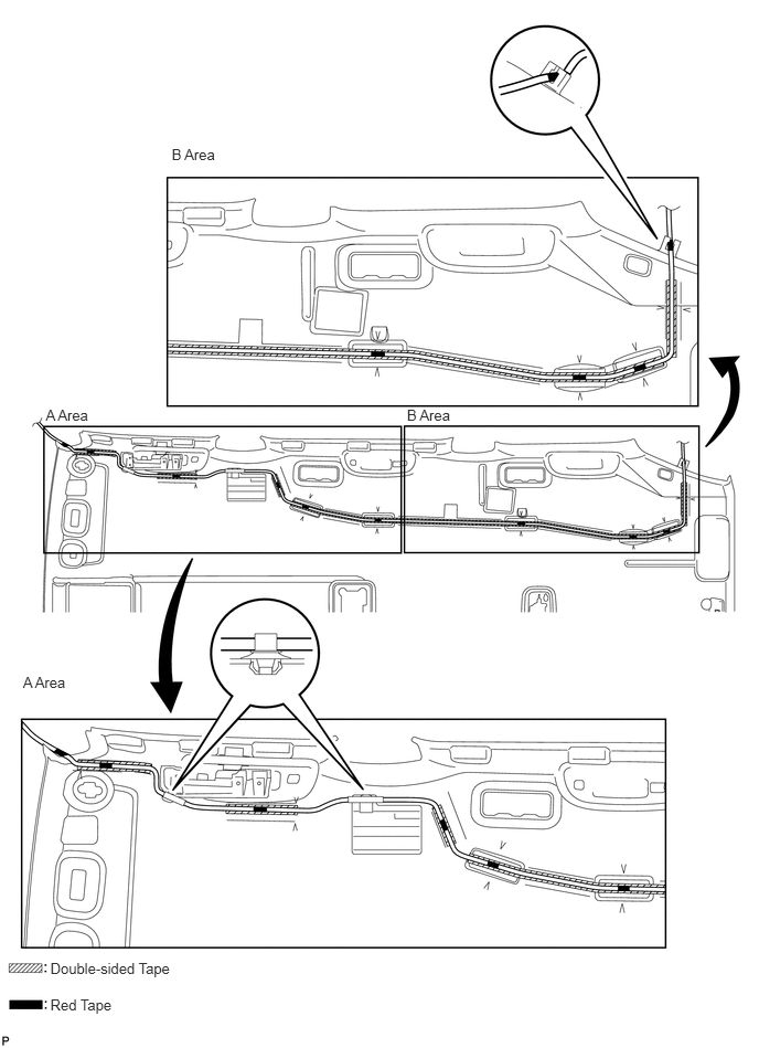
Align the red tape wound around the antenna cord with the V markings on the roof headlining and the notch at the rear of the headlining, and attach the antenna cord to the double-sided tape.
Attach the 2 clamps and fit the antenna into the notch.
w/ Sliding Roof:
Apply new double-sided tape as shown in the illustration.
- HINT:
-
Attach double-sided tape to the hatched areas shown in the illustration below.
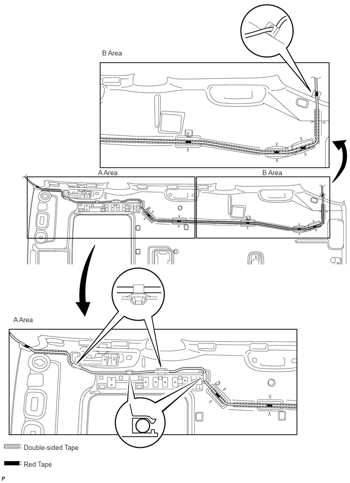 2.008,3.447 2.453,3.630 0.445,0.184 10 A Area 5.371,3.446 5.863,3.593 0.492,0.147 10 B Area 0.485,9.07 1.986,9.223 1.501,0.154 10 Double-sided Tape 0.487,9.418 1.233,9.560 0.746,0.142 10 Red Tape 0.274,6.457 0.719,6.641 0.445,0.184 10 A Area 2.091,1.002 2.584,1.149 0.492,0.147 10 B Area
Align the red tape wound around the antenna cord with the V markings on the roof headlining and the notch at the rear of the headlining, and attach the antenna cord to the double-sided tape.
Attach the 4 clamps and fit the antenna into the notch.
63310
4.INSTALL ROOF HEADLINING ASSEMBLY
w/o Sliding Roof:
Install the roof headlining (See page Vehicle Interior>INTERIOR PANELS / TRIM>ROOF HEADLINING (w/o Sliding Roof)>INSTALLATION).
w/ Sliding Roof:
Install the roof headlining (See page Vehicle Interior>INTERIOR PANELS / TRIM>ROOF HEADLINING (w/ Sliding Roof)>INSTALLATION).
86101
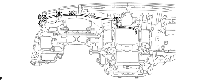
5.INSTALL ANTENNA CORD SUB-ASSEMBLY (w/o Multi-display)
for LHD:
Attach the 7 clamps to install the antenna cord.
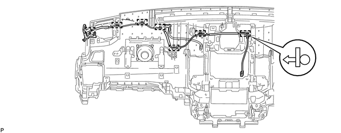
for RHD:
Attach the 5 clamps to install the antenna cord.
86101
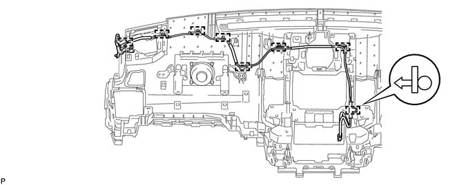
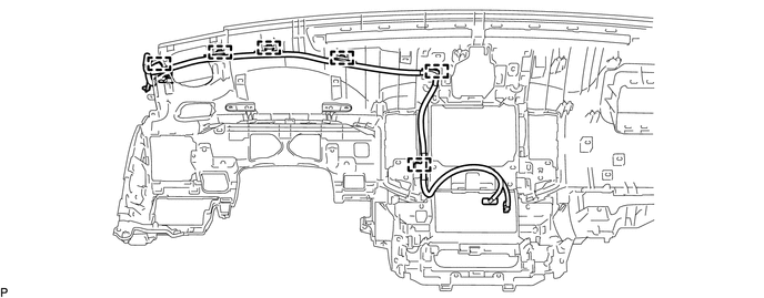
6.INSTALL ANTENNA CORD SUB-ASSEMBLY (w/ Multi-display)
for LHD:
Attach the 8 clamps to install the antenna cord.
for RHD:
Attach the 6 clamps to install the antenna cord.
55400
7.INSTALL INSTRUMENT PANEL SAFETY PAD ASSEMBLY
Install the instrument panel safety pad (See page Vehicle Interior>INTERIOR PANELS / TRIM>INSTRUMENT PANEL SAFETY PAD>INSTALLATION).
8.CONNECT CABLE TO NEGATIVE BATTERY TERMINAL
- NOTICE:
-
When disconnecting the cable, some systems need to be initialized after the cable is reconnected (See page General>INTRODUCTION>REPAIR INSTRUCTION>INITIALIZATION).
9.CHECK SRS WARNING LIGHT
Check the SRS warning light (See page Vehicle Interior>SUPPLEMENTAL RESTRAINT SYSTEMS>AIRBAG SYSTEM>DIAGNOSIS SYSTEM).