Home › Vehicle Exterior › SLIDING ROOF / CONVERTIBLE › SLIDING ROOF SYSTEM › 2014.08–2015.08
RM2660E _59 Vehicle Exterior _052851 SLIDING ROOF / CONVERTIBLE _0255742 SLIDING ROOF SYSTEM J

SLIDING ROOF / CONVERTIBLE  SLIDING ROOF SYSTEM  Sliding Roof Control Switch Circuit  


DESCRIPTION

The sliding roof drive gear (sliding roof ECU) receives slide switch and tilt switch signals and drives its built-in motor.

WIRING DIAGRAM
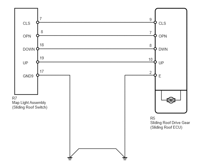
B181150E01
5.385,4.147 5.759,4.293 0.373,0.147 10 R5 1.419,0.579 1.792,0.726 0.373,0.147 10 7 1.463,1.057 1.836,1.203 0.373,0.147 10 8 1.419,1.519 1.792,1.666 0.373,0.147 10 18 1.419,1.991 1.792,2.137 0.373,0.147 10 19 1.419,2.473 1.792,2.620 0.373,0.147 10 17 5.684,0.747 6.058,0.893 0.373,0.147 10 CLS 5.684,1.212 6.058,1.359 0.373,0.147 10 OPN 5.684,1.674 6.216,1.821 0.531,0.147 10 DWN 5.684,2.168 6.058,2.314 0.373,0.147 10 UP 5.684,2.639 6.058,2.786 0.373,0.147 10 E 5.356,0.616 5.485,0.763 0.129,0.147 10 9 5.356,1.082 5.485,1.228 0.129,0.147 10 7 5.356,1.543 5.485,1.690 0.129,0.147 10 8 5.317,2.037 5.543,2.183 0.226,0.147 10 10 5.356,2.509 5.485,2.655 0.129,0.147 10 2 0.818,0.747 1.192,0.893 0.373,0.147 10 CLS 0.818,1.212 1.192,1.359 0.373,0.147 10 OPN 0.818,1.674 1.349,1.821 0.531,0.147 10 DOWN 0.818,2.168 1.192,2.314 0.373,0.147 10 UP 0.818,2.639 1.270,2.786 0.451,0.147 10 GND9 5.385,4.302 6.958,4.615 1.573,0.313 10 Sliding Roof Drive Gear (Sliding Roof ECU) 0.435,3.588 1.820,3.901 1.385,0.313 10 Map Light Assembly (Sliding Roof Switch) 0.435,3.432 0.774,3.635 0.339,0.203 10 R7

PROCEDURE

1.PERFORM ACTIVE TEST USING INTELLIGENT TESTER (SLIDING ROOF OPERATION)
a.

Select the Active Test, use the intelligent tester to generate a control command, and then check that the sliding roof slides open/closed and tilts up/down (See page Vehicle Exterior>SLIDING ROOF / CONVERTIBLE>SLIDING ROOF SYSTEM>DATA LIST / ACTIVE TEST).

Sliding Roof
Tester Display Test Part Control Range Diagnostic Note
Slide Roof Operate sliding roof SLIDE CLOSE/TILT UP CLOS/UP: Sliding roof SLIDE CLOSE or TILT UP operation occurs
OFF: Sliding roof is not operating
Be careful to avoid injuries as this test causes vehicle parts to move.
Slide Roof Operate sliding roof SLIDE OPEN/TILT DOWN OPEN/DWN: Sliding roof SLIDE OPEN or TILT DOWN operation occurs
OFF: Sliding roof is not operating
Be careful to avoid injuries as this test causes vehicle parts to move.


OK:

Sliding roof operates normally.


OK

2.READ VALUE USING INTELLIGENT TESTER (SLIDING ROOF SWITCH)

NG

REPLACE SLIDING ROOF DRIVE GEAR SUB-ASSEMBLY (SLIDING ROOF ECU)

2.READ VALUE USING INTELLIGENT TESTER (SLIDING ROOF SWITCH)
a.

Use the Data List to check if the sliding roof switch is functioning properly (See page Vehicle Exterior>SLIDING ROOF / CONVERTIBLE>SLIDING ROOF SYSTEM>DATA LIST / ACTIVE TEST).

Sliding Roof
Item Measurement Item/Range Normal Condition Diagnostic Note
Open Switch Sliding roof switch open signal/ON or OFF ON: OPEN switch is pressed
OFF: OPEN switch is not pressed
-
Close Switch Sliding roof switch close signal/ON or OFF ON: CLOSE switch is pressed
OFF: CLOSE switch is not pressed
-
Up Switch Sliding roof switch tilt up signal/ON or OFF ON: UP switch is pressed
OFF: UP switch is not pressed
-
Down Switch Sliding roof switch tilt down signal/ON or OFF ON: DOWN switch is pressed
OFF: DOWN switch is not pressed
-


OK:

When the switch is operating, the intelligent tester should display as shown in the table.


OK

REPLACE SLIDING ROOF DRIVE GEAR SUB-ASSEMBLY (SLIDING ROOF ECU)

NG

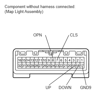
3.INSPECT MAP LIGHT ASSEMBLY (SLIDING ROOF SWITCH)
B237546E01
0.154,0.131 2.673,0.482 2.519,0.350 10 Component without harness connected: (Map Light Assembly) 1.12,1.098 1.468,1.245 0.348,0.147 10 OPN 2.355,1.098 2.703,1.245 0.348,0.147 10 CLS 1.535,2.866 1.756,3.013 0.221,0.147 10 UP 1.976,2.866 2.481,3.013 0.505,0.147 10 DOWN 2.698,2.866 3.120,3.013 0.422,0.147 10 GND9 2.768,2.232 2.903,2.866 false 2.238,2.866 2.632,2.237 false 1.652,2.866 2.483,2.242 false 1.93,1.984 2.32,1.183 false 1.793,1.984 1.53,1.183 false


b.

Measure the resistance according to the value(s) in the table below.

Standard Resistance:
Tester Connection Switch Condition Specified Condition
19 (UP) - 17 (GND9) UP switch is pressed Below 1 Ω
19 (UP) - 17 (GND9) UP switch is not pressed 10 kΩ or higher
18 (DOWN) - 17 (GND9) DOWN switch is pressed Below 1 Ω
18 (DOWN) - 17 (GND9) DOWN switch is not pressed 10 kΩ or higher
8 (OPN) - 17 (GND9) OPEN switch is pressed Below 1 Ω
8 (OPN) - 17 (GND9) OPEN switch is not pressed 10 kΩ or higher
7 (CLS) - 17 (GND9) CLOSE switch is pressed Below 1 Ω
7 (CLS) - 17 (GND9) CLOSE switch is not pressed 10 kΩ or higher


OK

4.CHECK HARNESS AND CONNECTOR (SLIDING ROOF DRIVE GEAR - MAP LIGHT)

NG

REPLACE MAP LIGHT ASSEMBLY (SLIDING ROOF SWITCH)

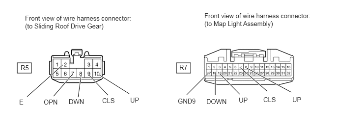
4.CHECK HARNESS AND CONNECTOR (SLIDING ROOF DRIVE GEAR - MAP LIGHT)
B449952E01
0.365,1.333 0.667,1.552 0.302,0.219 3.74,1.333 4.042,1.552 0.302,0.219 0.573,2.052 1.333,1.375 true 1.135,2.042 1.531,1.583 true 1.656,2.063 1.719,1.604 true 2.292,2.021 1.896,1.604 true 2.74,1.99 2.094,1.583 true 4.417,1.552 3.958,2.01 true 4.563,1.552 4.563,2.021 true 4.656,1.563 5.083,2 true 5.083,1.427 5.667,1.938 true 5.219,1.438 6.177,1.958 true 0.531,0.302 2.875,0.719 2.344,0.417 10 false Front view of wire harness connector: (to Sliding Roof Drive Gear) 0.438,1.354 0.729,1.583 0.292,0.229 10 false R5 0.406,2.083 0.625,2.302 0.219,0.219 10 false E 3.802,1.344 4.094,1.573 0.292,0.229 10 false R7 4.333,0.25 6.656,0.792 2.323,0.542 10 false Front view of wire harness connector: (to Map Light Assembly) 0.927,2.083 1.302,2.313 0.375,0.229 10 false OPN 1.458,2.073 1.885,2.292 0.427,0.219 10 false DWN 2.167,2.052 2.531,2.281 0.365,0.229 10 false CLS 2.76,2.042 3.042,2.271 0.281,0.229 10 false UP 3.771,2.063 4.24,2.281 0.469,0.219 10 false GND9 4.375,2.073 4.875,2.292 0.5,0.219 10 false DOWN 5.063,2.042 5.458,2.26 0.396,0.219 10 false UP 5.583,2.031 6,2.26 0.417,0.229 10 false CLS 6.198,2.031 6.531,2.26 0.333,0.229 10 false UP

a.

Disconnect the R5 drive gear connector.


b.

Disconnect the R7 map light connector.


c.

Measure the resistance according to the value(s) in the table below.

Standard Resistance:
Tester Connection Condition Specified Condition
R5-10 (UP) - R7-19 (UP) Always Below 1 Ω
R5-8 (DWN) - R7-18 (DOWN) Always Below 1 Ω
R5-7 (OPN) - R7-8 (OPN) Always Below 1 Ω
R5-9 (CLS) - R7-7 (CLS) Always Below 1 Ω
R7-17 (GND9) - Body ground Always Below 1 Ω
R5-2 (E) - Body ground Always Below 1 Ω
R5-10 (UP) or R7-19 (UP) - Body ground Always 10 kΩ or higher
R5-8 (DWN) or R7-18 (DOWN) - Body ground Always 10 kΩ or higher
R5-7 (OPN) or R7-8 (OPN) - Body ground Always 10 kΩ or higher
R5-9 (CLS) or R7-7 (CLS) - Body ground Always 10 kΩ or higher


OK

REPLACE SLIDING ROOF DRIVE GEAR SUB-ASSEMBLY (SLIDING ROOF ECU)

NG

REPAIR OR REPLACE HARNESS OR CONNECTOR