DOOR / HATCH POWER BACK DOOR SYSTEM Door Control Switch Circuit
DESCRIPTION
The back door control switch only turns on while the switch is being pressed, and turns off when the back door control switch is released.
When the back door control switch is on, a power back door close request signal is input to the power back door unit assembly (power back door ECU) to close the back door.
WIRING DIAGRAM
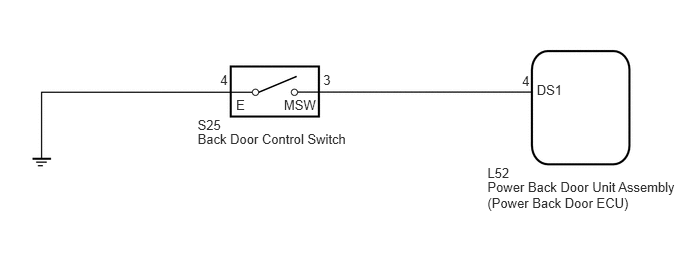
PROCEDURE
Check the Data List for proper functioning of the back door control switch (See page Vehicle Exterior>DOOR / HATCH>POWER BACK DOOR SYSTEM>DATA LIST / ACTIVE TEST).
| Tester Display | Measurement Item/Range | Normal Condition | Diagnostic Note |
|---|---|---|---|
| PBD Close SW | Back door control switch signal / ON or OFF | ON: Back door control switch on
OFF: Back door control switch off |
- |
- OK:
The display is as specified in the normal condition.
OK
NG
Remove the back door control switch (See page Vehicle Exterior>DOOR / HATCH>POWER BACK DOOR CONTROL SWITCH>REMOVAL).
Inspect the back door control switch (See page Vehicle Exterior>DOOR / HATCH>POWER BACK DOOR CONTROL SWITCH>INSPECTION).
OK
NG
Disconnect the S25 back door control switch connector.
Disconnect the L52 power back door unit assembly (power back door ECU) connector.
Measure the resistance of the wire harness side connectors.
- Standard Resistance:
Tester Connection Condition Specified Condition S25-3 (MSW) - L52-4 (DS1) Always Below 1 Ω S25-4 (E) - Body ground Always Below 1 Ω S25-3 (MSW) - Body ground Always 10 kΩ or higher
OK
NG