1VD-FTV EMISSION CONTROL DIFFERENTIAL PRESSURE SENSOR(for DPF) INSTALLATION
PROCEDURE

 89481B
1.INSTALL DIFFERENTIAL PRESSURE SENSOR ASSEMBLY
for Bank 1:
Install the differential pressure sensor with the bolt.
- Torque:
- 5.0 N*m (51 kgf*cm, 44 in.*lbf)
Install the sensor bracket with the bolt.
- Torque:
- 31 N*m (316 kgf*cm, 23 ft.*lbf)
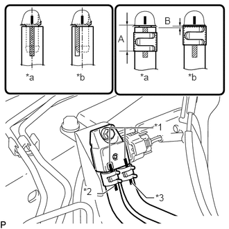
Install the No. 1 air hose and No. 2 air hose to the differential pressure sensor with 2 new clips.
- NOTICE:
- ·
Connect the air hoses so that the paint marks of the air hoses are as shown in the illustration.
·Make sure the end of the clip is 14.3 mm (0.563 in.) or less from the end of the exhaust pipe air hose when installing the clip as shown by A in the illustration.
·Make sure the clip does not protrude beyond the end of the hose as shown by B in the illustration.
| *1 | Marking |
| *2 | Purple Paint Mark |
| *3 | Yellow Green Paint Mark |
| *a | CORRECT |
| *b | INCORRECT |
Connect the differential pressure sensor connector.
for Bank 2:
Install the differential pressure sensor with the bolt.
- Torque:
- 14 N*m (137 kgf*cm, 10 ft.*lbf)
Install the sensor bracket with the bolt.
- Torque:
- 31 N*m (316 kgf*cm, 23 ft.*lbf)
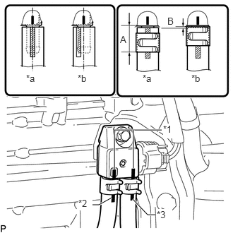
Install the No. 3 air hose and No. 4 air hose to the differential pressure sensor with 2 new clips.
- NOTICE:
- ·
Connect the air hoses so that the paint marks of the air hoses are as shown in the illustration.
·Make sure the end of the clip is 14.3 mm (0.563 in.) or less from the end of the exhaust pipe air hose when installing the clip as shown by A in the illustration.
·Make sure the clip does not protrude beyond the end of the hose as shown in by B the illustration.
| *1 | Marking |
| *2 | Light Blue Paint Mark |
| *3 | Red Paint Mark |
| *a | CORRECT |
| *b | INCORRECT |
Connect the differential pressure sensor connector and attach the clamp.
Attach the 4 wire harness clamps.
Install the front propeller shaft (Drivetrain>DRIVE SHAFT / PROPELLER SHAFT>FRONT PROPELLER SHAFT ASSEMBLY>INSTALLATION).