3UR-FE EMISSION CONTROL AIR SWITCHING VALVE(w/ Secondary Air Injection System) INSTALLATION
PROCEDURE

 17363Q
1.INSTALL NO. 3 AIR TUBE
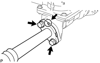
Install a new gasket and the No. 3 air tube with the 2 bolts.
- Torque:
- 10 N*m (102 kgf*cm, 7 ft.*lbf)
| *a | Identification Color |
- HINT:
-
The identification color on the flange is orange.
- NOTICE:
-
Make sure the claws on the gasket are not caught between the air tube and air switching valve.
17362
2.INSTALL NO. 2 AIR TUBE
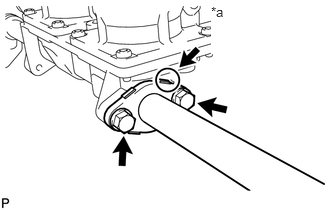
Install a new gasket and the No. 2 air tube with the 2 bolts.
- Torque:
- 10 N*m (102 kgf*cm, 7 ft.*lbf)
| *a | Identification Color |
- HINT:
-
The identification color on the flange is blue.
- NOTICE:
-
Make sure the claws on the gasket are not caught between the air tube and air switching valve.
25720
3.INSTALL AIR SWITCHING VALVE ASSEMBLY
Install the air switching valve assembly with the 3 bolts.
- Torque:
- 21 N*m (214 kgf*cm, 15 ft.*lbf)
Connect the 2 air switching valve connectors.
Install the bracket with the bolt.
- Torque:
- 8.0 N*m (82 kgf*cm, 71 in.*lbf)
Connect the knock sensor connector.
17303
4.INSTALL AIR PIPE SUB-ASSEMBLY
Connect the 2 No. 1 air hoses to the air pipe sub-assembly.
Connect the air pipe to the air switching valve assembly, and install the air pipe sub-assembly with the 2 bolts.
- Torque:
- 10 N*m (102 kgf*cm, 7 ft.*lbf)
Connect the air pump connector clamp holder.
Attach the wire harness claw.
Connect the air pump connector.
Connect the No. 3 hose to the air pipe sub-assembly, and slide the clip to secure the hose.
Connect the No. 2 hose to the air pipe sub-assembly, and slide the clip to secure the hose.
16355
5.INSTALL FRONT WATER BY-PASS JOINT
Install 2 new gaskets and the front water by-pass joint with the 4 nuts.
- Torque:
- 21 N*m (214 kgf*cm, 15 ft.*lbf)
Connect the engine coolant temperature sensor connector.
16268A
6.CONNECT NO. 2 WATER BY-PASS PIPE SUB-ASSEMBLY
Connect the No. 2 water by-pass pipe with the 3 bolts.
- Torque:
- 10 N*m (102 kgf*cm, 7 ft.*lbf)
16264D
7.CONNECT NO. 2 WATER BY-PASS HOSE
Connect the No. 2 water by-pass hose to the water by-pass joint, and slide the clip to secure the hose.
16261G
8.CONNECT NO. 1 WATER BY-PASS HOSE
Connect the No. 1 water by-pass hose to the water by-pass joint and water inlet housing, and slide the clip to secure the hose.
12611
9.INSTALL NO. 1 ENGINE COVER
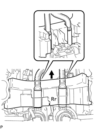
- HINT:
- ·
Align the No. 1 engine cover cutouts with the air tube.
·Align the No. 1 engine cover with the air switching valve surface and cylinder head wall.
- NOTICE:
-
Make sure that the No. 1 engine cover is flush with the top surface of the intake port of the cylinder head for bank 1 and bank 2.
77285H
10.CONNECT FUEL TUBE CLAMP
Connect the fuel tube clamp to the bracket.
11212
11.INSTALL NO. 2 ENGINE COVER
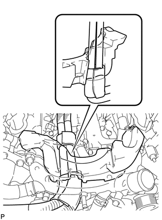
- HINT:
- ·
Align the No. 2 engine cover cutout with the air tube.
·Align the No. 2 engine cover with the front water by-pass joint and cylinder head wall.
- NOTICE:
-
Make sure that the No. 2 engine cover is flush with the top surface of the intake port of the cylinder head.
17111
12.INSTALL INTAKE MANIFOLD
Install the intake manifold (See page Engine / Hybrid System>3UR-FE (INTAKE / EXHAUST)>EXHAUST MANIFOLD>INSTALLATION).
13.INSTALL EXHAUST MANIFOLD SUB-ASSEMBLY
Install the exhaust manifold (See page Engine / Hybrid System>3UR-FE (INTAKE / EXHAUST)>EXHAUST MANIFOLD>INSTALLATION).