3UR-FE INTAKE / EXHAUST EXHAUST MANIFOLD INSTALLATION
PROCEDURE

 89467C
1.INSTALL AIR FUEL RATIO SENSOR (for Bank 2 Sensor 1)
89467B
2.INSTALL AIR FUEL RATIO SENSOR (for Bank 1 Sensor 1)
17104
3.INSTALL EXHAUST MANIFOLD SUB-ASSEMBLY RH
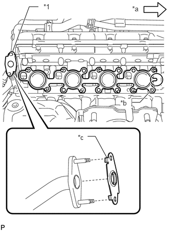
| *1 | No. 2 Air Tube |
| *a | Front |
| *b | Tab |
| *c | Claw |
w/ Secondary Air Injection System:
Install a new gasket to the cylinder head and a new gasket to the No. 2 air tube.
- HINT:
- ·
Install the exhaust manifold gasket with the gasket tab facing toward the front of the engine.
·Install the air tube gasket with the gasket claws facing the No. 2 air tube side.
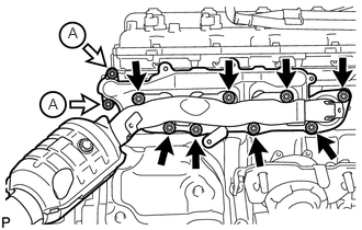
Temporarily install the exhaust manifold sub-assembly RH with the 2 nuts labeled A and 8 new nuts.
Uniformly tighten the nuts that are not labeled A, and then tighten the 2 nuts labeled A.
- Torque:
- for nut A : 10 N*m (102 kgf*cm, 7 ft.*lbf)
- except nut A : 21 N*m (214 kgf*cm, 15 ft.*lbf)
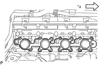
| *a | Front |
| *b | Tab |
w/o Secondary Air Injection System:
Install a new gasket to the cylinder head.
- HINT:
-
Install the exhaust manifold gasket with the gasket tab facing toward the front of the engine.
Temporarily install the exhaust manifold sub-assembly RH with the 8 new nuts.
Uniformly tighten the 8 nuts.
- Torque:
- 21 N*m (214 kgf*cm, 15 ft.*lbf)
Attach the wire harness clamp to the bracket and connect the connector.
17167
4.INSTALL NO. 1 EXHAUST MANIFOLD HEAT INSULATOR
Install the No. 1 exhaust manifold heat insulator with the 3 bolts.
- Torque:
- 10 N*m (102 kgf*cm, 7 ft.*lbf)
17118
5.INSTALL NO. 1 MANIFOLD STAY
Temporarily install the No. 1 manifold stay with the 3 bolts.
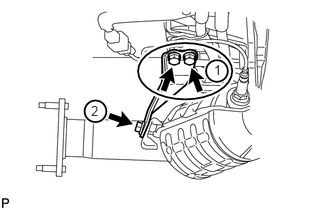
Tighten the 3 bolts in the order shown in the illustration.
- Torque:
- 40 N*m (408 kgf*cm, 30 ft.*lbf)
17105
6.INSTALL EXHAUST MANIFOLD SUB-ASSEMBLY LH
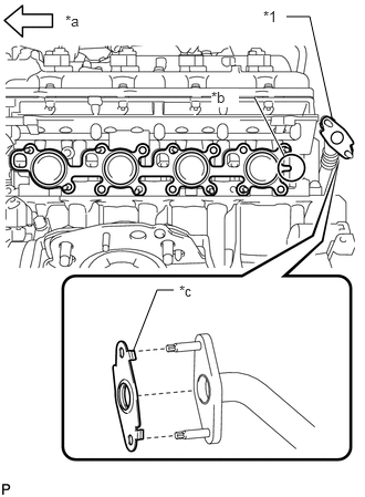
| *1 | No. 3 Air Tube |
| *a | Front |
| *b | Tab |
| *c | Claw |
w/ Secondary Air Injection System:
Install a new gasket to the cylinder head and a new gasket to the No. 3 air tube.
- HINT:
- ·
Install the exhaust manifold gasket with the gasket tab facing toward the rear of the engine.
·Install the air tube gasket with the gasket claws facing the No. 3 air tube side.
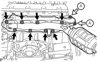
Temporarily install the exhaust manifold with the 2 nuts labeled A and 8 new nuts.
Uniformly tighten the nuts that are not labeled A, and then tighten the 2 nuts labeled A.
- Torque:
- for nut A : 10 N*m (102 kgf*cm, 7 ft.*lbf)
- except nut A : 21 N*m (214 kgf*cm, 15 ft.*lbf)
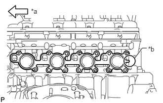
| *a | Front |
| *b | Tab |
w/o Secondary Air Injection System:
Install a new gasket to the cylinder head.
- HINT:
-
Install the exhaust manifold gasket with the gasket tab facing toward the rear of the engine.
Temporarily install the exhaust manifold sub-assembly LH with the 8 new nuts.
Uniformly tighten the 8 nuts.
- Torque:
- 21 N*m (214 kgf*cm, 15 ft.*lbf)
Attach the wire harness clamp to the bracket and connect the connector.
17168
7.INSTALL NO. 2 EXHAUST MANIFOLD HEAT INSULATOR
Install the No. 2 exhaust manifold heat insulator with the 3 bolts.
- Torque:
- 10 N*m (102 kgf*cm, 7 ft.*lbf)
17119
8.INSTALL NO. 2 MANIFOLD STAY
Temporarily install the No. 2 manifold stay with the 3 bolts.
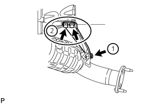
Tighten the 3 bolts in the order shown in the illustration.
- Torque:
- 40 N*m (408 kgf*cm, 30 ft.*lbf)
37117
9.INSTALL PROPELLER SHAFT HEAT INSULATOR
Install the propeller shaft heat insulator with the 2 bolts.
- Torque:
- 16 N*m (160 kgf*cm, 12 ft.*lbf)
17410
10.INSTALL FRONT EXHAUST PIPE ASSEMBLY
17450B
11.INSTALL FRONT NO. 2 EXHAUST PIPE ASSEMBLY
17420
12.INSTALL CENTER EXHAUST PIPE ASSEMBLY
17430
13.INSTALL TAILPIPE ASSEMBLY
11452
14.INSTALL ENGINE OIL LEVEL DIPSTICK GUIDE
15.INSPECT FOR EXHAUST GAS LEAK
If gas is leaking, tighten the areas necessary to stop the leak. Replace damaged parts as necessary.
53737B
16.INSTALL FRONT FENDER APRON SEAL LH
Install the front fender apron seal LH with the 3 clips.
53739A
17.INSTALL FRONT FENDER APRON SEAL REAR LH
Install the front fender apron seal rear LH with the 4 clips.
53736G
18.INSTALL FRONT FENDER APRON SEAL FRONT RH
Install the front fender apron seal front RH with the 3 clips.
53738A
19.INSTALL FRONT FENDER APRON SEAL REAR RH
Install the front fender apron seal rear RH with the 4 clips.
51441
20.INSTALL NO. 1 ENGINE UNDER COVER SUB-ASSEMBLY
53806
21.INSTALL FRONT FENDER SPLASH SHIELD SUB-ASSEMBLY LH
53805
22.INSTALL FRONT FENDER SPLASH SHIELD SUB-ASSEMBLY RH
51442
23.INSTALL NO. 2 ENGINE UNDER COVER