Home › Power Source / Network › NETWORKING › CAN COMMUNICATION SYSTEM (for RHD without Central Gateway ECU) › from 2017.08
RM2660E _57 Power Source / Network _052837 NETWORKING _0255538 CAN COMMUNICATION SYSTEM(for RHD without Central Gateway ECU) J

NETWORKING  CAN COMMUNICATION SYSTEM(for RHD without Central Gateway ECU)  Short to B+ in CAN Bus Line  


DESCRIPTION

There may be a short circuit between the CAN bus lines and +B when the resistance between terminals 6 (CANH) and 16 (BAT) or terminals 14 (CANL) and 16 (BAT) of the DLC3 is below 6 kΩ.

Detection Item Trouble Area
The resistance between terminals 6 (CANH) and 16 (BAT) or terminals 14 (CANL) and 16 (BAT) of the DLC3 is below 6 kΩ.
·

Short between CAN bus lines and +B

·

ECM

·

4WD control ECU

·

Power steering ECU assembly*1

·

Airbag sensor assembly

·

Tire pressure warning ECU*2

·

Air conditioning amplifier assembly

·

Central gateway ECU

·

Main body ECU (multiplex network body ECU)

·

Master cylinder solenoid (skid control ECU)

·

Headlight leveling ECU assembly

·

Certification ECU (smart key ECU assembly)*3

·

Steering control ECU*4

·

Multi-media module receiver assembly*5

·

Option connector*6

·

Steering sensor

·

Combination meter assembly

·

DLC3 CAN branch wire or connector

·

No. 1 CAN junction connector

·

No. 2 CAN junction connector


*1: w/ Variable Flow Control Solenoid Valve

*2: w/ Tire Pressure Warning System

*3: w/ Entry and Start System

*4: w/ Variable Gear Ratio Steering System

*5: for Multi-media Module Receiver Assembly

*6: w/ Option Connector


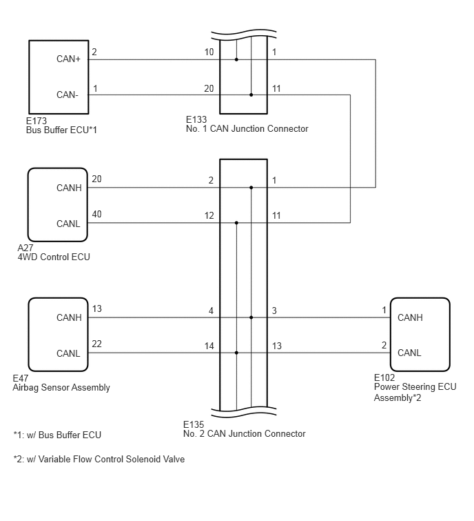
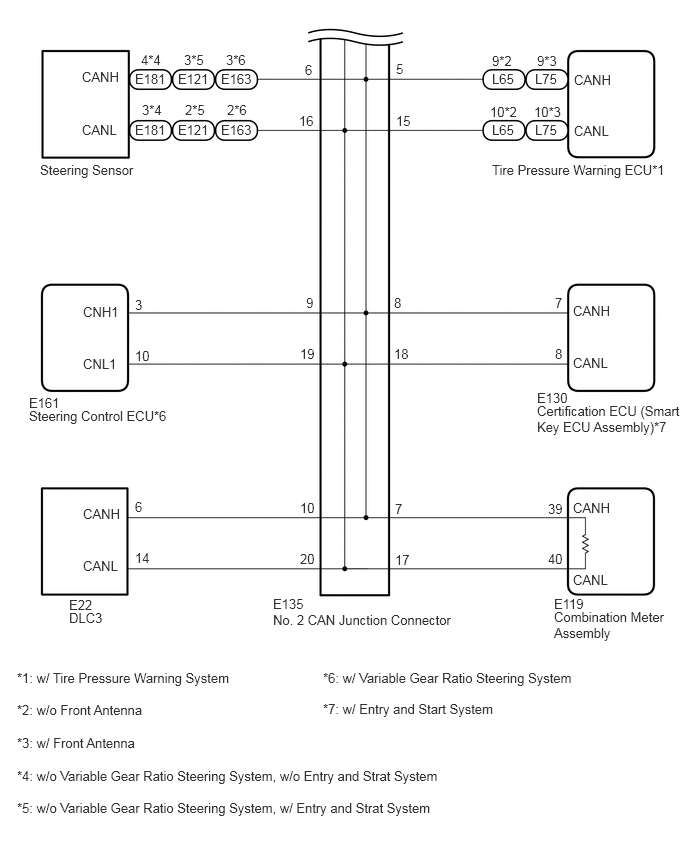
WIRING DIAGRAM
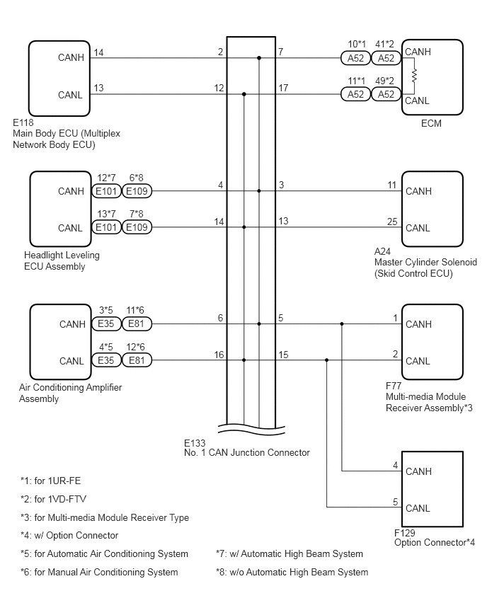
C348517E02
5.115,1.302 5.427,1.573 0.313,0.271 10 false A52 5.563,1.302 5.927,1.563 0.365,0.26 10 false A52 5.115,0.771 5.458,1.031 0.344,0.26 10 false A52 5.563,0.771 5.885,0.99 0.323,0.219 10 false A52 6.198,1.729 6.688,2.052 0.49,0.323 10 false ECM 5.958,1.396 6.469,1.615 0.51,0.219 10 false CANL 5.958,0.677 6.51,0.917 0.552,0.24 10 false CANH 5.521,0.563 6.052,0.792 0.531,0.229 10 false 41*2 5.115,0.563 5.51,0.802 0.396,0.24 10 false 10*1 5.521,1.104 6.052,1.323 0.531,0.219 10 false 49*2 5.115,1.104 5.542,1.344 0.427,0.24 10 false 11*1 4.094,0.677 4.594,0.906 0.5,0.229 10 false 7 4.094,1.208 4.594,1.469 0.5,0.26 10 false 17 3.208,0.677 3.667,0.948 0.458,0.271 10 false 2 3.146,1.208 3.583,1.5 0.438,0.292 10 false 12 0.854,1.313 1.385,1.635 0.531,0.323 10 false CANL 0.854,0.76 1.323,1.052 0.469,0.292 10 false CANH 1.375,1.208 1.833,1.479 0.458,0.271 10 false 13 1.375,0.688 1.781,0.969 0.406,0.281 10 false 14 0.188,1.719 0.708,1.906 0.521,0.188 10 false E118 0.188,1.875 1.833,2.469 1.646,0.594 10 false Main Body ECU (Multiplex Network Body ECU) 5.51,3.615 5.875,3.802 0.365,0.188 10 false A24 5.51,3.771 7.052,4.396 1.542,0.625 10 false Master Cylinder Solenoid (Skid Control ECU) 5.969,3.271 6.5,3.542 0.531,0.271 10 false CANL 5.969,2.729 6.5,2.958 0.531,0.229 10 false CANH 5.698,2.635 6.031,2.906 0.333,0.271 10 false 11 5.698,3.177 6.031,3.438 0.333,0.26 10 false 25 4.104,2.635 4.573,2.875 0.469,0.24 10 false 3 4.094,3.167 4.552,3.438 0.458,0.271 10 false 13 3.208,2.635 3.469,2.875 0.26,0.24 10 false 4 3.146,3.177 3.49,3.438 0.344,0.26 10 false 14 0.854,3.271 1.354,3.573 0.5,0.302 10 false CANL 0.854,2.729 1.417,2.99 0.563,0.26 10 false CANH 1.427,3.063 1.823,3.26 0.396,0.198 10 false 13*7 1.427,2.531 1.885,2.76 0.458,0.229 10 false 12*7 1.406,3.26 1.792,3.521 0.385,0.26 10 false E101 1.406,2.729 1.802,2.948 0.396,0.219 10 false E101 1.906,3.063 2.375,3.271 0.469,0.208 10 false 7*8 1.906,2.531 2.302,2.833 0.396,0.302 10 false 6*8 1.854,3.26 2.271,3.479 0.417,0.219 10 false E109 1.854,2.729 2.229,2.948 0.375,0.219 10 false E109 0.354,3.667 1.531,4.375 1.177,0.708 10 false Headlight Leveling ECU Assembly 0.302,6.99 2.781,7.25 2.479,0.26 10 false *1: for 1UR-FE 0.302,7.26 2.771,7.51 2.469,0.25 10 false *2: for 1VD-FTV 0.302,7.531 2.979,7.823 2.677,0.292 10 false *3: for Multi-media Module Receiver Type 0.302,7.792 3.031,8.083 2.729,0.292 10 false *4: w/ Option Connector 0.302,8.063 3.094,8.354 2.792,0.292 10 false *5: for Automatic Air Conditioning System 0.302,8.333 3.063,8.698 2.76,0.365 10 false *6: for Manual Air Conditioning System 3.177,8.063 5.844,8.354 2.667,0.292 10 false *7: w/ Automatic High Beam System 3.177,8.333 5.823,8.698 2.646,0.365 10 false *8: w/o Automatic High Beam System 0.281,5.615 1.885,6.365 1.604,0.75 10 false Air Conditioning Amplifier Assembly 0.875,5.229 1.417,5.427 0.542,0.198 10 false CANL 0.875,4.688 1.448,4.969 0.573,0.281 10 false CANH 4.094,4.594 4.583,4.854 0.49,0.26 10 false 5 4.094,5.135 4.604,5.417 0.51,0.281 10 false 15 3.208,4.594 3.708,4.917 0.5,0.323 10 false 6 3.146,5.135 3.573,5.417 0.427,0.281 10 false 16 1.896,5.219 2.26,5.458 0.365,0.24 10 false E81 1.854,5.021 2.375,5.24 0.521,0.219 10 false 12*6 1.885,4.677 2.24,4.906 0.354,0.229 10 false E81 1.854,4.479 2.365,4.667 0.51,0.188 10 false 11*6 1.438,5.219 1.813,5.438 0.375,0.219 10 false E35 1.458,5.021 1.896,5.229 0.438,0.208 10 false 4*5 1.438,4.677 1.813,4.906 0.375,0.229 10 false E35 1.458,4.479 1.958,4.688 0.5,0.208 10 false 3*5 2.708,6.438 3.146,6.635 0.438,0.198 10 false E133 2.708,6.573 4.802,7.115 2.094,0.542 10 false No. 1 CAN Junction Connector 5.969,5.229 6.552,5.479 0.583,0.25 10 false CANL 5.969,4.688 6.521,4.979 0.552,0.292 10 false CANH 5.781,4.594 6.104,4.885 0.323,0.292 10 false 1 5.781,5.125 6.021,5.354 0.24,0.229 10 false 2 5.677,5.594 6.104,5.823 0.427,0.229 10 false F77 5.677,5.75 7.073,6.625 1.396,0.875 10 false Multi-media Module Receiver Assembly*3 5.969,7.396 6.573,7.688 0.604,0.292 10 false CANL 5.969,6.854 6.51,7.146 0.542,0.292 10 false CANH 5.781,6.76 6,6.979 0.219,0.219 10 false 4 5.781,7.302 6.042,7.552 0.26,0.25 10 false 5 5.802,7.76 6.313,8.021 0.51,0.26 10 false F129 5.802,7.896 7.115,8.417 1.313,0.521 10 false Option Connector*4

C344594E01
2.811,1.72 3.172,1.869 0.361,0.149 10 E133 2.811,1.857 5.219,2.006 2.408,0.149 10 No. 1 CAN Junction Connector 4.109,4.601 4.612,4.750 0.503,0.149 10 3 4.109,5.137 4.612,5.286 0.503,0.149 10 13 3.153,4.601 3.656,4.750 0.503,0.149 10 4 3.086,5.137 3.589,5.286 0.503,0.149 10 14 2.769,6.318 3.130,6.467 0.361,0.149 10 E135 2.769,6.455 5.177,6.604 2.408,0.149 10 No. 2 CAN Junction Connector 0.191,5.62 0.552,5.768 0.361,0.149 10 E47 0.191,5.756 1.875,6.104 1.684,0.348 10 Airbag Sensor Assembly 0.852,5.252 1.355,5.401 0.503,0.149 10 CANL 0.852,4.708 1.355,4.857 0.503,0.149 10 CANH 1.389,4.571 1.892,4.720 0.503,0.149 10 13 1.389,5.107 1.892,5.256 0.503,0.149 10 22 6.009,5.24 6.512,5.389 0.503,0.149 10 CANL 6.009,4.708 6.512,4.857 0.503,0.149 10 CANH 5.655,5.611 6.071,5.760 0.416,0.149 10 E102 5.655,5.748 6.980,6.066 1.325,0.318 10 Power Steering ECU Assembly*2 5.771,5.13 6.274,5.279 0.503,0.149 10 2 5.771,4.593 6.274,4.742 0.503,0.149 10 1 0.203,6.845 3.537,6.994 3.334,0.149 10 *2: w/ Variable Flow Control Solenoid Valve 0.203,6.481 3.537,6.630 3.334,0.149 10 *1: w/ Bus Buffer ECU 4.109,2.635 4.612,2.784 0.503,0.149 10 1 4.109,3.171 4.612,3.320 0.503,0.149 10 11 3.153,2.635 3.656,2.784 0.503,0.149 10 2 3.086,3.171 3.589,3.320 0.503,0.149 10 12 0.852,3.29 1.355,3.439 0.503,0.149 10 CANL 0.852,2.747 1.355,2.896 0.503,0.149 10 CANH 1.389,2.61 1.892,2.759 0.503,0.149 10 20 1.389,3.146 1.892,3.294 0.503,0.149 10 40 0.266,3.655 0.627,3.804 0.361,0.149 10 A27 0.266,3.792 1.985,3.941 1.718,0.149 10 4WD Control ECU 4.109,0.694 4.612,0.843 0.503,0.149 10 1 4.109,1.246 4.612,1.395 0.503,0.149 10 11 3.086,0.694 3.589,0.843 0.503,0.149 10 10 3.086,1.246 3.589,1.395 0.503,0.149 10 20 0.852,1.349 1.355,1.498 0.503,0.149 10 CAN- 0.852,0.805 1.355,0.954 0.503,0.149 10 CAN+ 1.389,0.694 1.892,0.843 0.503,0.149 10 2 1.403,1.246 1.906,1.395 0.503,0.149 10 1 0.392,1.742 0.753,1.891 0.361,0.149 10 E173 0.392,1.878 2.111,2.027 1.718,0.149 10 Bus Buffer ECU*1

C344595E05
5.594,4.063 5.958,4.208 0.365,0.146 10 false E130 5.594,4.198 7.135,4.542 1.542,0.344 10 false Certification ECU (Smart Key ECU Assembly)*7 5.969,3.698 6.469,3.844 0.5,0.146 10 false CANL 5.969,3.156 6.469,3.302 0.5,0.146 10 false CANH 5.781,3.073 6.281,3.219 0.5,0.146 10 false 7 5.781,3.604 6.281,3.75 0.5,0.146 10 false 8 4.104,3.073 4.604,3.219 0.5,0.146 10 false 8 4.104,3.604 4.604,3.75 0.5,0.146 10 false 18 0.865,3.708 1.365,3.854 0.5,0.146 10 false CNL1 0.865,3.167 1.365,3.313 0.5,0.146 10 false CNH1 1.406,3.625 1.906,3.771 0.5,0.146 10 false 10 1.406,3.094 1.906,3.24 0.5,0.146 10 false 3 0.302,4.115 0.667,4.26 0.365,0.146 10 false E161 0.302,4.25 2.406,4.396 2.104,0.146 10 false Steering Control ECU*6 3.188,3.073 3.688,3.219 0.5,0.146 10 false 9 3.125,3.604 3.625,3.75 0.5,0.146 10 false 19 0.865,5.813 1.365,5.958 0.5,0.146 10 false CANL 0.865,5.271 1.365,5.417 0.5,0.146 10 false CANH 1.406,5.729 1.906,5.875 0.5,0.146 10 false 14 1.406,5.198 1.906,5.344 0.5,0.146 10 false 6 0.719,6.219 1.083,6.365 0.365,0.146 10 false E22 0.719,6.354 2.823,6.5 2.104,0.146 10 false DLC3 3.125,5.208 3.625,5.354 0.5,0.146 10 false 10 3.125,5.74 3.625,5.885 0.5,0.146 10 false 20 5.771,6.208 6.208,6.354 0.438,0.146 10 false E119 5.771,6.344 7.031,6.688 1.26,0.344 10 false Combination Meter Assembly 5.969,5.958 6.469,6.104 0.5,0.146 10 false CANL 5.969,5.208 6.469,5.354 0.5,0.146 10 false CANH 5.708,5.219 6.208,5.365 0.5,0.146 10 false 39 5.708,5.74 6.208,5.885 0.5,0.146 10 false 40 4.115,5.219 4.615,5.365 0.5,0.146 10 false 7 4.115,5.75 4.615,5.896 0.5,0.146 10 false 17 2.844,6.375 4.927,6.625 2.083,0.25 10 false No. 2 CAN Junction Connector 2.844,6.208 3.281,6.354 0.438,0.146 10 false E135 3.177,0.646 3.677,0.792 0.5,0.146 10 false 6 3.115,1.177 3.615,1.323 0.5,0.146 10 false 16 0.854,1.271 1.354,1.417 0.5,0.146 10 false CANL 0.854,0.719 1.354,0.865 0.5,0.146 10 false CANH 1.479,1.063 1.979,1.208 0.5,0.146 10 false 3*4 1.469,0.542 1.969,0.688 0.5,0.146 10 false 4*4 1.927,1.063 2.427,1.208 0.5,0.146 10 false 2*5 1.917,0.542 2.417,0.688 0.5,0.146 10 false 3*5 2.365,1.063 2.865,1.208 0.5,0.146 10 false 2*6 2.354,0.542 2.854,0.688 0.5,0.146 10 false 3*6 0.417,1.688 2,2.052 1.583,0.365 10 false Steering Sensor 4.125,0.635 4.625,0.781 0.5,0.146 10 false 5 4.125,1.177 4.625,1.323 0.5,0.146 10 false 15 1.406,0.74 1.771,0.885 0.365,0.146 10 false E181 1.406,1.271 1.771,1.417 0.365,0.146 10 false E181 1.854,0.74 2.219,0.885 0.365,0.146 10 false E121 1.854,1.271 2.219,1.417 0.365,0.146 10 false E121 2.302,0.74 2.667,0.885 0.365,0.146 10 false E163 2.302,1.271 2.667,1.417 0.365,0.146 10 false E163 5.125,0.74 5.49,0.885 0.365,0.146 10 false L65 5.125,1.271 5.49,1.417 0.365,0.146 10 false L65 5.573,0.74 5.938,0.885 0.365,0.146 10 false L75 5.573,1.271 5.938,1.417 0.365,0.146 10 false L75 5.979,1.281 6.479,1.427 0.5,0.146 10 false CANL 5.979,0.75 6.479,0.896 0.5,0.146 10 false CANH 5.104,1.083 5.604,1.229 0.5,0.146 10 false 10*2 5.125,0.552 5.625,0.698 0.5,0.146 10 false 9*2 5.563,1.083 6.063,1.229 0.5,0.146 10 false 10*3 5.594,0.552 6.094,0.698 0.5,0.146 10 false 9*3 5.125,1.688 7.042,1.833 1.917,0.146 10 false Tire Pressure Warning ECU*1 0.177,6.979 3.51,7.125 3.333,0.146 10 false *1: w/ Tire Pressure Warning System 0.177,7.313 2.635,7.458 2.458,0.146 10 false *2: w/o Front Antenna 0.177,7.656 2.635,7.802 2.458,0.146 10 false *3: w/ Front Antenna 0.177,8 5.333,8.146 5.156,0.146 10 false *4: w/o Variable Gear Ratio Steering System, w/o Entry and Strat System 0.177,8.333 5.333,8.479 5.156,0.146 10 false *5: w/o Variable Gear Ratio Steering System, w/ Entry and Strat System 3.365,7.302 5.469,7.448 2.104,0.146 10 false *7: w/ Entry and Start System 3.365,6.979 6.333,7.125 2.969,0.146 10 false *6: w/ Variable Gear Ratio Steering System

CAUTION / NOTICE / HINT

NOTICE:
·

Before measuring the resistance of the CAN bus, turn the ignition switch off and leave the vehicle for 1 minute or more without operating the key, switches or opening or closing the doors. After that, disconnect the cable from the negative (-) battery terminal and leave the vehicle for 1 minute or more before measuring the resistance.

·

After turning the ignition switch off, waiting time may be required before disconnecting the cable from the battery terminal. Therefore, make sure to read the disconnecting the cable from the battery terminal notice before proceeding with work (See page General>INTRODUCTION>REPAIR INSTRUCTION>PRECAUTION).

·

Inspect the fuses for circuits related to this system before performing the following inspection procedure.


HINT:
·

Operating the ignition switch, any switches or any doors triggers related ECU and sensor communication with the CAN, which causes resistance variation.

·

Even after DTCs are cleared, if a DTC is stored again after driving the vehicle for a while, the malfunction may be occurring due to vibration of the vehicle. In such a case, wiggling the ECUs or wire harness while performing the inspection below may help determine the cause of the malfunction.


PROCEDURE
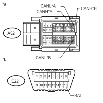
1.CHECK FOR SHORT TO B+ IN CAN BUS WIRE (ECM - NO. 1 CAN JUNCTION CONNECTOR)
a.
U165118E01
0.081,0.049 0.369,0.202 0.288,0.152 10 *a 0.081,1.893 0.369,2.045 0.288,0.152 10 *b 0.25,1.023 0.520,1.162 0.270,0.139 10 A52 0.382,2.621 0.656,2.760 0.274,0.139 10 E22 2.202,2.904 2.35,3.182 2.35,3.182 2.466,3.182 false 2.483,3.104 2.771,3.246 0.288,0.142 10 BAT 2.456,1.223 2.589,0.272 2.589,0.272 2.67,0.272 false 1.219,0.306 1.831,0.448 0.612,0.142 10 CANH*A 1.353,0.116 1.942,0.258 0.589,0.142 10 CANL*A 1.904,0.384 2.015,0.384 2.015,0.384 2.362,0.815 false 1.904,1.931 2.015,1.931 2.015,1.931 2.448,1.348 false 2.025,0.212 2.135,0.212 2.135,0.212 2.448,0.815 false 2.697,0.197 3.282,0.339 0.585,0.142 10 CANH*B 1.192,1.846 1.782,1.988 0.589,0.142 10 CANL*B

Disconnect the cable from the negative (-) battery terminal.


b.

Disconnect the ECM connector.


c.

Measure the resistance according to the value(s) in the table below.

Standard Resistance:
for 1UR-FE:
Tester Connection Condition Specified Condition
A52-10 (CANH) - E22-16 (BAT) Cable disconnected from negative (-) battery terminal 6 kΩ or higher
A52-11 (CANL) - E22-16 (BAT) Cable disconnected from negative (-) battery terminal 6 kΩ or higher

for 1VD-FTV:
Tester Connection Condition Specified Condition
A52-41 (CANH) - E22-16 (BAT) Cable disconnected from negative (-) battery terminal 6 kΩ or higher
A52-49 (CANL) - E22-16 (BAT) Cable disconnected from negative (-) battery terminal 6 kΩ or higher


Text in Illustration
*A for 1UR-FE
*B for 1VD-FTV
*a Front view of wire harness connector
(to ECM)
*b Front view of DLC3

Result
Result Proceed to
OK (for 1UR-FE) A
OK (for 1VD-FTV) B
NG C


A

B

C

2.CONNECT CONNECTOR
2.CONNECT CONNECTOR
a.

Reconnect the A52 ECM connector.


NEXT

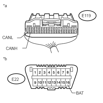
3.CHECK FOR SHORT TO B+ IN CAN BUS WIRE (COMBINATION METER ASSEMBLY - NO. 2 CAN JUNCTION CONNECTOR)
a.
U165148E01
0.104,0.101 0.392,0.254 0.288,0.152 10 *a 0.104,1.873 0.392,2.025 0.288,0.152 10 *b 2.726,0.439 3.092,0.578 0.366,0.139 10 E119 0.388,2.558 0.661,2.696 0.274,0.139 10 E22 2.259,2.823 2.407,3.101 2.407,3.101 2.523,3.101 false 2.54,3.023 2.828,3.165 0.288,0.142 10 BAT 0.938,1.069 0.685,1.264 0.685,1.264 0.569,1.264 false 1.018,1.074 0.876,1.605 0.876,1.605 0.744,1.605 false 0.076,1.171 0.564,1.313 0.487,0.142 10 CANL 0.196,1.534 0.684,1.676 0.487,0.142 10 CANH

Disconnect the combination meter assembly connector.


b.

Measure the resistance according to the value(s) in the table below.

Standard Resistance:
Tester Connection Condition Specified Condition
E119-39 (CANH) - E22-16 (BAT) Cable disconnected from negative (-) battery terminal 6 kΩ or higher
E119-40 (CANL) - E22-16 (BAT) Cable disconnected from negative (-) battery terminal 6 kΩ or higher


Text in Illustration
*a Rear view of wire harness connector
(to Combination Meter Assembly)
*b Front view of DLC3


OK

REPLACE COMBINATION METER ASSEMBLY

NG

4.CONNECT CONNECTOR
4.CONNECT CONNECTOR
a.

Reconnect the E119 combination meter assembly connector.


NEXT

5.CHECK FOR SHORT TO B+ IN CAN BUS WIRE (NO. 1 CAN JUNCTION CONNECTOR)
HINT:

If there is a short to B+ in the connection line while accessory parts are not connected, repair or replace the CAN bus branch line or connector.


a.

Disconnect the No. 1 CAN junction connector.
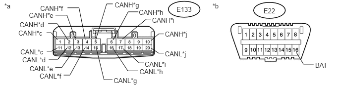
U165495E01
0.09,0.045 0.315,0.215 0.225,0.170 10 *a 4.466,0.045 4.691,0.215 0.225,0.170 10 *b 0.387,0.613 0.956,0.757 0.569,0.144 10 CANH*c 0.429,1.014 0.998,1.157 0.569,0.144 10 CANL*c 0.469,1.177 1.039,1.321 0.569,0.144 10 CANL*d 1.025,1.247 1.217,1.247 1.217,1.247 1.405,1.013 false 0.623,1.363 1.193,1.506 0.569,0.144 10 CANL*e 0.833,1.518 1.403,1.662 0.569,0.144 10 CANL*f 0.609,0.244 1.179,0.387 0.569,0.144 10 CANH*e 0.413,0.433 0.983,0.577 0.569,0.144 10 CANH*d 0.846,0.099 1.415,0.242 0.569,0.144 10 CANH*f 3.196,0.344 3.765,0.487 0.569,0.144 10 CANH*i 3.466,0.639 4.035,0.782 0.569,0.144 10 CANH*j 3.466,1.052 4.035,1.196 0.569,0.144 10 CANL*j 2.411,0.018 2.981,0.162 0.569,0.144 10 CANH*g 2.919,0.176 3.489,0.319 0.569,0.144 10 CANH*h 3.042,1.27 3.611,1.414 0.569,0.144 10 CANL*i 2.933,1.428 3.503,1.571 0.569,0.144 10 CANL*h 2.389,1.61 2.958,1.754 0.569,0.144 10 CANL*g 2.566,0.825 3.076,0.402 3.076,0.402 3.174,0.402 false 2.01,0.844 2.24,0.082 2.24,0.082 2.371,0.082 false 1.208,0.839 1.075,0.69 1.075,0.69 0.977,0.69 false 1.011,0.499 1.203,0.499 1.203,0.499 1.433,0.847 false 1.165,0.32 1.406,0.32 1.406,0.32 1.587,0.836 false 1.419,0.164 1.66,0.164 1.66,0.164 1.792,0.831 false 2.374,0.841 2.694,0.248 2.694,0.248 2.907,0.248 false 2.58,1.021 2.925,1.325 2.925,1.325 3.023,1.325 false 2.024,1.017 2.186,1.681 2.186,1.681 2.363,1.681 false 1.208,1.007 1.082,1.079 1.082,1.079 0.984,1.079 false 1.025,1.247 1.217,1.247 1.217,1.247 1.405,1.013 false 1.16,1.424 1.296,1.424 1.296,1.424 1.587,1.01 false 1.338,1.583 1.468,1.583 1.468,1.583 1.778,1.015 false 2.374,1.02 2.686,1.493 2.686,1.493 2.9,1.493 false 5.54,0.142 5.809,0.284 0.269,0.142 10 E22 6.624,1.287 7.013,1.430 0.389,0.144 10 BAT 6.227,1.104 6.377,1.352 6.377,1.352 6.591,1.352 false 3.709,0.119 4.053,0.261 0.343,0.142 10 E133 3.173,0.853 3.334,0.714 3.334,0.714 3.443,0.714 false 3.173,1.013 3.334,1.12 3.334,1.12 3.443,1.12 false

Text in Illustration
*a Front view of wire harness connector
(to No. 1 CAN Junction Connector)
*b Front view of DLC3
*c to No. 2 CAN Junction Connector *d to Main Body ECU (Multiplex Network Body ECU)
*e to Master Cylinder Solenoid (Skid Control ECU) *f to Headlight Leveling ECU Assembly
*g
·

to Multi-media Module Receiver Assembly (for Multi-media Module Receiver Type)

·

to Option Connector (w/ Option Connector)


*h to Air Conditioning Amplifier Assembly
*i to ECM *j to Bus Buffer ECU (w/ Bus Buffer ECU)


b.

Measure the resistance according to the value(s) in the table below.

Standard Resistance:
Tester Connection Condition Specified Condition Connect to
E133-1 (CANH) - E22-16 (BAT) Cable disconnected from negative (-) battery terminal 6 kΩ or higher No. 2 CAN junction connector
E133-11 (CANL) - E22-16 (BAT) Cable disconnected from negative (-) battery terminal 6 kΩ or higher
E133-2 (CANH) - E22-16 (BAT) Cable disconnected from negative (-) battery terminal 6 kΩ or higher Main body ECU (multiplex network body ECU)
E133-12 (CANL) - E22-16 (BAT) Cable disconnected from negative (-) battery terminal 6 kΩ or higher
E133-3 (CANH) - E22-16 (BAT) Cable disconnected from negative (-) battery terminal 6 kΩ or higher Master cylinder solenoid (skid control ECU)
E133-13 (CANL) - E22-16 (BAT) Cable disconnected from negative (-) battery terminal 6 kΩ or higher
E133-4 (CANH) - E22-16 (BAT) Cable disconnected from negative (-) battery terminal 6 kΩ or higher Headlight leveling ECU assembly
E133-14 (CANL) - E22-16 (BAT) Cable disconnected from negative (-) battery terminal 6 kΩ or higher
E133-5 (CANH) - E22-16 (BAT) Cable disconnected from negative (-) battery terminal 6 kΩ or higher
·

Multi-media module receiver assembly*1

·

Option connector*2


E133-15 (CANL) - E22-16 (BAT) Cable disconnected from negative (-) battery terminal 6 kΩ or higher
E133-6 (CANH) - E22-16 (BAT) Cable disconnected from negative (-) battery terminal 6 kΩ or higher Air conditioning amplifier assembly
E133-16 (CANL) - E22-16 (BAT) Cable disconnected from negative (-) battery terminal 6 kΩ or higher
E133-7 (CANH) - E22-16 (BAT) Cable disconnected from negative (-) battery terminal 6 kΩ or higher ECM
E133-17 (CANL) - E22-16 (BAT) Cable disconnected from negative (-) battery terminal 6 kΩ or higher
E133-10 (CANH) - E22-16 (BAT) Cable disconnected from negative (-) battery terminal 6 kΩ or higher Bus buffer ECU*3
E133-20 (CANL) - E22-16 (BAT) Cable disconnected from negative (-) battery terminal 6 kΩ or higher


*1: for Multi-media Module Receiver Type

*2: w/ Option Connector

*3: w/ Bus Buffer ECU


Result
Result Proceed to
OK A
NG (ECM CAN main wire) B
NG (No. 2 CAN junction connector CAN main wire) C
NG (ECU or sensor CAN branch wires) D


A

REPLACE NO. 1 CAN JUNCTION CONNECTOR

B

REPAIR OR REPLACE CAN MAIN WIRE OR CONNECTOR (NO. 1 CAN JUNCTION CONNECTOR - ECM)

C

6.CONNECT CONNECTOR

D

8.CHECK FOR SHORT TO B+ IN CAN BUS WIRE (ECU, SENSOR)
6.CONNECT CONNECTOR
a.

Reconnect the E133 No. 1 CAN junction connector.


NEXT

7.CHECK FOR SHORT TO B+ IN CAN BUS WIRE (NO. 2 CAN JUNCTION CONNECTOR)
a.

Disconnect the No. 2 CAN junction connector.
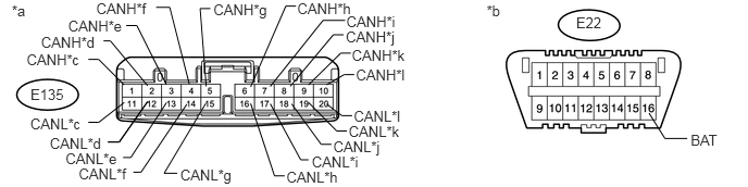
U165496E01
0.113,0.019 0.339,0.189 0.225,0.170 10 *a 4.662,0.019 4.887,0.189 0.225,0.170 10 *b 0.292,0.819 0.635,0.961 0.343,0.142 10 E135 0.256,0.493 0.826,0.636 0.569,0.144 10 CANH*c 0.291,1.107 0.861,1.250 0.569,0.144 10 CANL*c 0.478,1.291 1.048,1.434 0.569,0.144 10 CANL*d 1.034,1.36 1.142,1.36 1.142,1.36 1.414,0.973 false 0.629,1.434 1.199,1.578 0.569,0.144 10 CANL*e 0.755,1.58 1.325,1.723 0.569,0.144 10 CANL*f 0.654,0.169 1.223,0.312 0.569,0.144 10 CANH*e 0.394,0.326 0.964,0.470 0.569,0.144 10 CANH*d 0.923,0.004 1.493,0.148 0.569,0.144 10 CANH*f 3.314,0.274 3.883,0.418 0.569,0.144 10 CANH*j 3.371,0.45 3.940,0.594 0.569,0.144 10 CANH*k 2.849,0 3.419,0.144 0.569,0.144 10 CANH*h 2.046,0.013 2.615,0.157 0.569,0.144 10 CANH*g 3.319,0.123 3.889,0.266 0.569,0.144 10 CANH*i 3.194,1.328 3.764,1.472 0.569,0.144 10 CANL*j 3.341,1.18 3.911,1.323 0.569,0.144 10 CANL*k 2.745,1.614 3.315,1.758 0.569,0.144 10 CANL*h 2.78,0.827 3.193,0.333 3.193,0.333 3.291,0.333 false 2.401,0.832 2.738,0.058 2.738,0.058 2.836,0.058 false 0.992,0.392 1.058,0.392 1.058,0.392 1.414,0.821 false 1.209,0.245 1.311,0.245 1.311,0.245 1.594,0.81 false 1.496,0.07 1.626,0.07 1.626,0.07 1.813,0.805 false 2.589,0.828 3.094,0.195 3.094,0.195 3.307,0.195 false 2.794,0.995 3.077,1.383 3.077,1.383 3.175,1.383 false 2.401,0.991 2.63,1.685 2.63,1.685 2.728,1.685 false 2.955,0.813 3.264,0.509 3.264,0.509 3.362,0.509 false 1.975,0.827 1.917,0.082 1.917,0.082 2.015,0.082 false 2.955,0.981 3.226,1.255 3.226,1.255 3.324,1.255 false 1.19,0.813 0.945,0.569 0.945,0.569 0.846,0.569 false 1.19,0.981 0.945,1.172 0.945,1.172 0.846,1.172 false 1.034,1.36 1.142,1.36 1.142,1.36 1.414,0.973 false 1.179,1.509 1.253,1.509 1.253,1.509 1.594,0.984 false 1.277,1.649 1.351,1.649 1.351,1.649 1.79,0.998 false 1.698,1.66 1.572,1.66 1.572,1.66 1.971,0.991 false 2.988,1.466 3.558,1.610 0.569,0.144 10 CANL*i 2.589,0.994 2.881,1.531 2.881,1.531 2.955,1.531 false 5.52,0.139 5.792,0.287 0.272,0.148 10 E22 6.617,1.261 6.969,1.404 0.352,0.144 10 BAT 6.218,1.083 6.37,1.326 6.37,1.326 6.584,1.326 false 1.728,1.595 2.298,1.738 0.569,0.144 10 CANL*g 3.411,0.64 3.981,0.784 0.569,0.144 10 CANH*l 3.128,0.812 3.296,0.715 3.296,0.715 3.394,0.715 false 3.39,1.033 3.960,1.176 0.569,0.144 10 CANL*l 3.128,0.995 3.275,1.108 3.275,1.108 3.373,1.108 false

Text in Illustration
*a Front view of wire harness connector
(to No. 2 CAN Junction Connector)
*b Front view of DLC3
*c to No. 1 CAN Junction Connector *d to 4WD Control ECU
*e to Power Steering ECU Assembly (w/ Variable Flow Control Solenoid Valve) *f to Airbag Sensor Assembly
*g to Tire Pressure Warning ECU (w/ Tire Pressure Warning System) *h to Steering Sensor
*i to Combination Meter Assembly *j to Certification ECU (Smart Key ECU Assembly) (w/ Entry and Start System)
*k to Steering Control ECU (w/ Variable Gear Ratio Steering System) *l to DLC3


b.

Measure the resistance according to the value(s) in the table below.

Standard Resistance:
Tester Connection Condition Specified Condition Connect to
E135-1 (CANH) - E22-16 (BAT) Cable disconnected from negative (-) battery terminal 6 kΩ or higher No. 1 CAN junction connector
E135-11 (CANL) - E22-16 (BAT) Cable disconnected from negative (-) battery terminal 6 kΩ or higher
E135-2 (CANH) - E22-16 (BAT) Cable disconnected from negative (-) battery terminal 6 kΩ or higher 4WD control ECU
E135-12 (CANL) - E22-16 (BAT) Cable disconnected from negative (-) battery terminal 6 kΩ or higher
E135-3 (CANH) - E22-16 (BAT) Cable disconnected from negative (-) battery terminal 6 kΩ or higher Power steering ECU assembly*1
E135-13 (CANL) - E22-16 (BAT) Cable disconnected from negative (-) battery terminal 6 kΩ or higher
E135-4 (CANH) - E22-16 (BAT) Cable disconnected from negative (-) battery terminal 6 kΩ or higher Airbag sensor assembly
E135-14 (CANL) - E22-16 (BAT) Cable disconnected from negative (-) battery terminal 6 kΩ or higher
E135-5 (CANH) - E22-16 (BAT) Cable disconnected from negative (-) battery terminal 6 kΩ or higher Tire pressure warning ECU*2
E135-15 (CANL) - E22-16 (BAT) Cable disconnected from negative (-) battery terminal 6 kΩ or higher
E135-6 (CANH) - E22-16 (BAT) Cable disconnected from negative (-) battery terminal 6 kΩ or higher Steering sensor
E135-16 (CANL) - E22-16 (BAT) Cable disconnected from negative (-) battery terminal 6 kΩ or higher
E135-7 (CANH) - E22-16 (BAT) Cable disconnected from negative (-) battery terminal 6 kΩ or higher Combination meter assembly
E135-17 (CANL) - E22-16 (BAT) Cable disconnected from negative (-) battery terminal 6 kΩ or higher
E135-8 (CANH) - E22-16 (BAT) Cable disconnected from negative (-) battery terminal 6 kΩ or higher Certification ECU (smart key ECU assembly)*3
E135-18 (CANL) - E22-16 (BAT) Cable disconnected from negative (-) battery terminal 6 kΩ or higher
E135-9 (CANH) - E22-16 (BAT) Cable disconnected from negative (-) battery terminal 6 kΩ or higher Steering control ECU*4
E135-19 (CANL) - E22-16 (BAT) Cable disconnected from negative (-) battery terminal 6 kΩ or higher
E135-10 (CANH) - E22-16 (BAT) Cable disconnected from negative (-) battery terminal 6 kΩ or higher DLC3
E135-20 (CANL) - E22-16 (BAT) Cable disconnected from negative (-) battery terminal 6 kΩ or higher


*1: w/ Variable Flow Control Solenoid Valve

*2: w/ Tire Pressure Warning System

*3: w/ Entry and Start System

*4: w/ Variable Gear Ratio Steering System


Result
Result Proceed to
OK A
NG (Combination meter assembly CAN main wire) B
NG (No. 1 CAN junction connector CAN main wire) C
NG (DLC3 CAN branch wires) D
NG (ECU or sensor CAN branch wires) E


A

REPLACE NO. 2 CAN JUNCTION CONNECTOR

B

REPAIR OR REPLACE CAN MAIN WIRE OR CONNECTOR (NO. 2 CAN JUNCTION CONNECTOR - COMBINATION METER ASSEMBLY)

C

REPAIR OR REPLACE CAN MAIN WIRE OR CONNECTOR (NO. 2 CAN JUNCTION CONNECTOR - NO. 1 CAN JUNCTION CONNECTOR)

D

REPAIR OR REPLACE CAN BRANCH WIRE CONNECTED TO DLC3 (CANH, CANL)

E

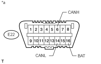
8.CHECK FOR SHORT TO B+ IN CAN BUS WIRE (ECU, SENSOR)
a.
U165235E02
1.948,0.906 2.135,0.417 2.135,0.417 2.271,0.417 false 2.323,1.479 2.469,1.906 2.469,1.906 2.604,1.906 false 1.948,1.479 1.802,1.906 1.802,1.906 1.667,1.906 false 0.052,0 0.354,0.188 0.302,0.188 10 false *a 2.313,0.333 2.781,0.521 0.469,0.188 10 false CANH 1.208,1.813 1.615,2 0.406,0.188 10 false CANL 2.646,1.823 3.052,2.01 0.406,0.188 10 false BAT 0.26,1.094 0.656,1.302 0.396,0.208 10 false E22

Reconnect the CAN junction connector.


b.

Disconnect the connector that includes terminals CANH and CANL from the ECU or sensor to which the bus line shorted to +B is connected


c.

Measure the resistance according to the value(s) in the table below.

Standard Resistance:
Tester Connection Condition Specified Condition
E22-6 (CANH) - E22-16 (BAT) Cable disconnected from negative (-) battery terminal 6 kΩ or higher
E22-14 (CANL) - E22-16 (BAT) Cable disconnected from negative (-) battery terminal 6 kΩ or higher


Text in Illustration
*a Front view of DLC3

HINT:

If the resistance changes to 6 kΩ or higher when the connector is disconnected from the ECU or sensor, there may be a short in the ECU or sensor.


OK

REPLACE CORRESPONDING ECU OR SENSOR

NG

REPAIR OR REPLACE CORRESPONDING ECU OR SENSOR CAN BRANCH WIRES OR CONNECTOR