Home › Audio / Visual / Telematics › NAVIGATION / MULTI INFO DISPLAY › NAVIGATION SYSTEM › from 2018.08
RM2660E _56 Audio / Visual / Telematics _052829 NAVIGATION / MULTI INFO DISPLAY _0255494 NAVIGATION SYSTEM C

NAVIGATION / MULTI INFO DISPLAY  NAVIGATION SYSTEM  B1574  GVIF Disconnected (from Park Assist/Monitoring ECU to EMV/MM Integrated Device)  


DESCRIPTION

DTC Code DTC Detection Condition Trouble Area
B1574 GVIF disconnected (from Parking assist ECU to Multi-display)
·

Harness or connector (GVIF cable)

·

Multi-display assembly


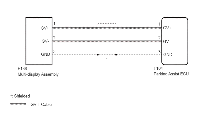
WIRING DIAGRAM

E330010E07
1.365,0.854 1.823,1.094 0.458,0.24 10 false GV+ 1.396,1.292 1.865,1.521 0.469,0.229 10 false GV- 0.594,2.208 1.375,2.417 0.781,0.208 10 false F136 5.458,0.844 5.958,1.083 0.5,0.24 10 false GV+ 5.458,1.302 5.917,1.51 0.458,0.208 10 false GV- 5.469,1.74 5.99,1.958 0.521,0.219 10 false GND 1.781,0.708 7.156,0.979 5.375,0.271 10 false 1 1.781,1.177 7.156,1.448 5.375,0.271 10 false 2 1.781,1.635 2.969,1.906 1.188,0.271 10 false 3 5.302,1.646 6.49,1.917 1.188,0.271 10 false 3 5.302,1.177 7.156,1.458 1.854,0.281 10 false 2 5.302,0.719 7.156,1 1.854,0.281 10 false 1 0.594,2.396 2.479,2.625 1.885,0.229 10 false Multi-display Assembly 5.146,2.198 5.573,2.448 0.427,0.25 10 false F104 5.146,2.385 7.156,2.563 2.01,0.177 10 false Parking Assist ECU 3.552,1.896 4.74,2.167 1.188,0.271 10 false * 0.344,3.125 2.229,3.354 1.885,0.229 10 false *: Shielded 0.948,3.406 2.833,3.635 1.885,0.229 10 false : GVIF Cable 1.375,1.729 1.844,1.99 0.469,0.26 10 false GND

PROCEDURE

2.CHECK DTC
a.

Recheck for DTCs and check if the same DTC is output again (See page Audio / Visual / Telematics>NAVIGATION / MULTI INFO DISPLAY>NAVIGATION SYSTEM>DTC CHECK / CLEAR).

OK:

No DTCs are output.


OK

NG

3.CHECK HARNESS AND CONNECTOR (GVIF CABLE)
a.

Check that the digital signal lines between the multi-display assembly and parking assist ECU are not sharply bent or pinched, and that the connectors are properly connected and there are no other installation problems.

OK:

There are no installation problems.


OK

4.REPLACE HARNESS AND CONNECTOR (GVIF CABLE)

NG

REPLACE HARNESS AND CONNECTOR (GVIF CABLE)

4.REPLACE HARNESS AND CONNECTOR (GVIF CABLE)
a.
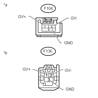
E402587E03
1.521,0.875 1.052,0.573 1.052,0.573 1,0.573 true 1.885,0.906 2.354,0.635 2.354,0.635 2.417,0.635 true 1.823,1.021 2.104,1.5 2.104,1.5 2.167,1.5 true 1.583,2.604 1.198,2.438 1.198,2.438 1.135,2.438 true 1.833,2.615 2.156,2.448 2.156,2.448 2.219,2.448 true 1.771,2.823 2.167,3.135 2.167,3.135 2.229,3.135 true 1.521,1.708 1.875,1.896 0.354,0.188 10 false F136 1.542,0.208 1.896,0.396 0.354,0.188 10 false F104 2.479,0.552 2.938,0.75 0.458,0.198 10 false GV- 0.635,0.5 1.24,0.677 0.604,0.177 10 false GV+ 2.25,1.417 2.854,1.594 0.604,0.177 10 false GND 2.271,2.385 2.875,2.563 0.604,0.177 10 false GV- 0.792,2.344 1.396,2.521 0.604,0.177 10 false GV+ 2.302,3.042 2.906,3.219 0.604,0.177 10 false GND 0.125,0.083 0.729,0.26 0.604,0.177 10 false *a 0.125,1.771 0.729,1.948 0.604,0.177 10 false *b

Disconnect the F136 multi-display assembly connector.


b.

Disconnect the F104 parking assist ECU connector.


c.

Measure the resistance according to the value(s) in the table below.

Standard Resistance:
Tester Connection Condition Specified Condition
F136-1 (GV+) - F104-1 (GV+) Always Below 1 Ω
F136-2 (GV-) - F104-2 (GV-) Always Below 1 Ω
F136-3 (GND) - F104-3 (GND) Always Below 1 Ω
F136-1 (GV+) - Body ground Always 10 kΩ or higher
F136-2 (GV-) - Body ground Always 10 kΩ or higher
F136-3 (GND) - Body ground Always 10 kΩ or higher


Text in Illustration
*a Front view of wire harness connector
(to Parking Assist ECU)
*b Front view of wire harness connector
(to Multi-display Assembly)


OK

NG

REPLACE HARNESS AND CONNECTOR (GVIF CABLE)