BRAKE SYSTEM (OTHER) BRAKE BOOSTER PUMP INSTALLATION
CAUTION / NOTICE / HINT
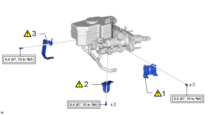
| Procedure | Part Name Code |

|

|

|
|
|---|---|---|---|---|---|
| 1 | NO. 2 BRAKE POWER SUPPLY BRACKET | - | ( ) |
- | - |
| 2 | NO. 1 BRAKE POWER SUPPLY BRACKET | - | () |
- | - |
| 3 | NO. 2 WIRE CLAMP BRACKET | - | () |
- | - |

|
Tightening torque for "Major areas involving basic vehicle performance such as moving/turning/stopping": N*m (kgf*cm, ft.*lbf) | - | - |
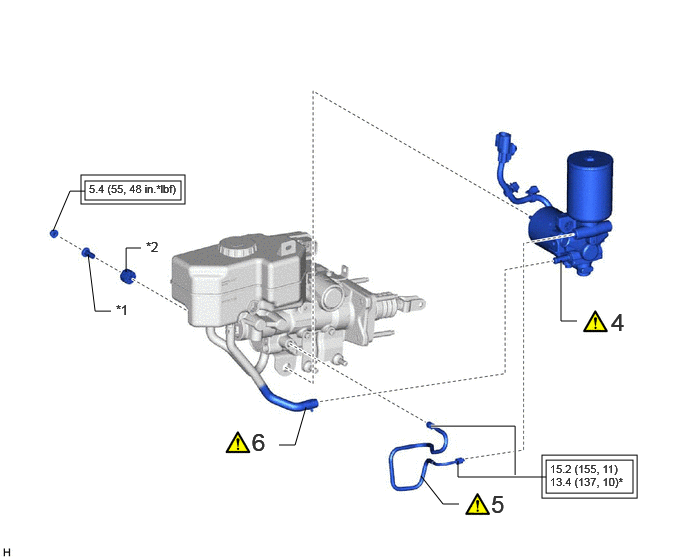
| Procedure | Part Name Code |
|
|
|
|
|---|---|---|---|---|---|
| 4 | BRAKE BOOSTER PUMP WITH ACCUMULATOR ASSEMBLY | - | () |
- | - |
| 5 | NO. 1 BRAKE ACTUATOR TUBE | - | () |
- | - |
| 6 | NO. 2 RESERVOIR HOSE | - | () |
- | - |
| *1 | BRAKE ACTUATOR CASE COLLAR | *2 | BRAKE BOOSTER PUMP BUSHING |
|
|
Tightening torque for "Major areas involving basic vehicle performance such as moving/turning/stopping": N*m (kgf*cm, ft.*lbf) | * | For use with a union nut wrench |
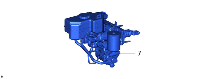
| Procedure | Part Name Code |
|
|
|
|
|---|---|---|---|---|---|
| 7 | BRAKE BOOSTER WITH MASTER CYLINDER ASSEMBLY | 47210L | - | - | - |
CAUTION / NOTICE / HINT
- NOTICE:
-
 0.688,0.5 0.938,0.5 false 0.75,1 1,1 false 0.833,1.5 1.083,1.5 false 1.031,1.833 1.281,1.833 false 2.667,1.833 2.917,1.833 false 2.292,1.5 2.458,1.417 2.458,1.417 2.625,1.417 false 2.375,0.667 2.625,0.667 false 1.719,0.99 1.885,0.406 1.885,0.406 2.052,0.406 true 2.677,0.604 3.01,0.854 0.333,0.25 10 false *a 0.573,0.938 0.906,1.188 0.333,0.25 10 false *b 2.969,1.771 3.219,2.021 0.25,0.25 10 false *c 2.677,1.354 2.927,1.604 0.25,0.25 10 false *d 0.51,0.438 0.844,0.604 0.333,0.167 10 false *e 0.688,1.438 0.938,1.688 0.25,0.25 10 false *f 2.094,0.344 2.344,0.594 0.25,0.25 10 false *g 0.865,1.771 1.198,2.021 0.333,0.25 10 false *h
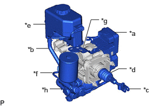
*a No. 1 Skid Control ECU *b No. 1 Reservoir Hose and No. 2 Reservoir Hose *c Master Cylinder Push Rod Clevis *d Boot *e Brake Master Cylinder Reservoir *f No. 1 Brake Actuator Tube *g No. 1 Wire Clamp Bracket *h Brake Booster with Accumulator Pump Assembly
-
Do not carry the brake master cylinder with pump assembly by the parts shown in the illustration.
PROCEDURE

 1.INSTALL NO. 2 BRAKE POWER SUPPLY BRACKET
|
|
|
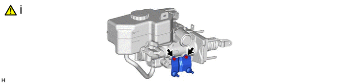
Using a 5 mm long hexagon socket wrench, install the No. 2 brake power supply bracket with the 2 bolts.
- Torque:
- 6.6 N*m (67 kgf*cm, 58 in.*lbf)
2.INSTALL NO. 1 BRAKE POWER SUPPLY BRACKET
|
|
|
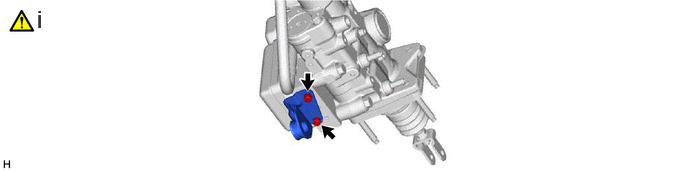
Using a 5 mm long hexagon socket wrench, install the No. 1 brake power supply bracket with the 2 bolts.
- Torque:
- 6.6 N*m (67 kgf*cm, 58 in.*lbf)
3.INSTALL NO. 2 WIRE CLAMP BRACKET
|
|
|
for LHD:
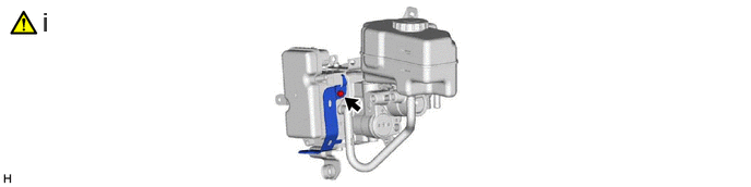
Using a 5 mm long hexagon socket wrench, install the No. 2 wire clamp bracket with the bolt.
- Torque:
- 6.6 N*m (67 kgf*cm, 58 in.*lbf)
47070B 4.INSTALL BRAKE BOOSTER PUMP WITH ACCUMULATOR ASSEMBLY
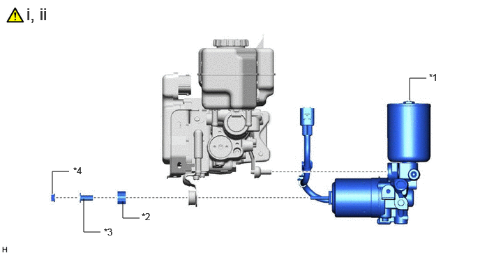
| *1 | Brake Booster Pump With Accumulator Assembly | *2 | Brake Booster Pump Bushing |
| *3 | Brake Actuator Case Collar | *4 | Nut |
Install the brake booster pump with accumulator assembly, brake booster pump bushing and brake actuator case collar with the nut to the brake booster with master cylinder assembly as shown in the illustration.
- Torque:
- 5.4 N*m (55 kgf*cm, 48 in.*lbf)
Engage the 3 clamps to the brake booster with master cylinder assembly.
5.INSTALL NO. 1 BRAKE ACTUATOR TUBE
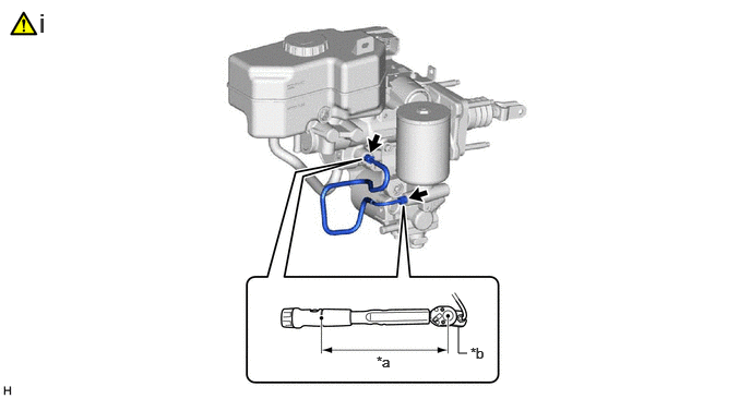
| *a | Torque Wrench Fulcrum Length | *b | Union Nut Wrench |
Using a union nut wrench, install the No. 1 brake actuator tube.
- Torque:
- Specified tightening torque : 15.2 N*m (155 kgf*cm, 11 ft.*lbf)
- NOTICE:
-
·
Do not kink or damage the brake line.
·Do not allow any foreign matter such as dirt or dust to enter the brake line from the connecting parts.
- HINT:
-
·
Calculate the torque wrench reading when changing the fulcrum length of the torque wrench.
Click hereGeneral>INTRODUCTION>REPAIR INSTRUCTION>PRECAUTION
·When using a union nut wrench (fulcrum length of 22 mm (0.866 in.)) + torque wrench (fulcrum length of 162 mm (6.38 in.)):
13.4 N*m (137 kgf*cm, 10 ft.*lbf)
6.CONNECT NO. 2 RESERVOIR HOSE
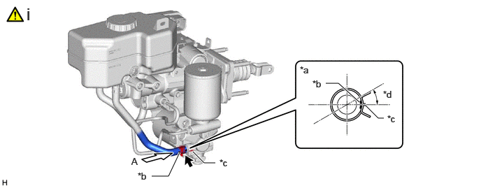
| *a | View A | *b | Paint Mark |
| *c | Rib | *d | within 45° |
Connect the No. 2 reservoir hose to the brake booster with accumulator pump assembly and slide the clip to secure it.
- NOTICE:
-
·
Make sure that the paint mark is outside of the Vehicle.
·Install the clip within the range shown in the illustration.
47210L 7.INSTALL BRAKE BOOSTER WITH MASTER CYLINDER ASSEMBLY
for LHD:
Click hereBrake>BRAKE SYSTEM (OTHER)>BRAKE BOOSTER (for LHD)>INSTALLATION
for RHD:
Click hereBrake>BRAKE SYSTEM (OTHER)>BRAKE BOOSTER (for RHD)>INSTALLATION