RM38G0E _58 Vehicle Interior _100440 POWER OUTLETS (INT) _0467294 VOLTAGE INVERTER A
POWER OUTLETS (INT) VOLTAGE INVERTER INSTALLATION
CAUTION / NOTICE / HINT
COMPONENTS (INSTALLATION)
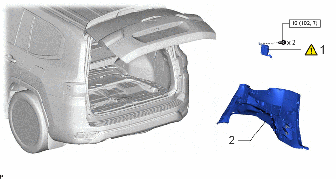
6.167,0.417 6.833,0.583 0.667,0.167 5.083,3 5.333,3 5.333,3 5.667,2.583 false 5.708,1.052 6.417,1.052 false 6.031,0.854 6.031,0.5 6.031,0.5 6.167,0.5 false 4.875,2.833 5.125,3.167 0.25,0.333 18 false 2 6.813,0.906 7.063,1.24 0.25,0.333 18 false 1 6.125,0.813 6.375,0.979 0.25,0.167 10 false x 2 6.219,0.417 6.885,0.583 0.667,0.167 8 false 10 (102, 7)
| Procedure | Part Name Code |

|

|

|
|
|---|---|---|---|---|---|
| 1 | VOLTAGE INVERTER ASSEMBLY | 86210A | ( ) |
- | - |
| 2 | QUARTER TRIM PANEL ASSEMBLY LH | 62520B | - | - | - |

|
N*m (kgf*cm, ft.*lbf): Specified torque | - | - |
PROCEDURE

 86210A 1.INSTALL VOLTAGE INVERTER ASSEMBLY
a.
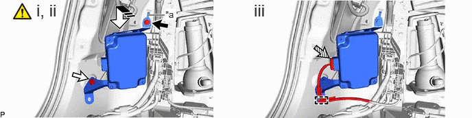
2.25,0.229 2.5,0.229 true 0.552,0.01 1.052,0.51 0.5,0.5 18 false i, ii 3.854,0.01 4.354,0.51 0.5,0.5 18 false iii 2.51,0.135 2.677,0.302 0.167,0.167 10 true *a
| *a | Hook | - | - |

|
Bolt A |

|
Bolt B |

|
Connector |

|
Temporarily Install in this Direction |
i.
Temporarily install the voltage inverter assembly to the vehicle body.
- HINT:
-
Hook the hook into the vehicle body hole.
ii.
Install the 2 bolts.
- Torque:
- 10 N*m (102 kgf*cm, 7 ft.*lbf)
- HINT:
-
Tightening order: Temporarily install bolt A and bolt B → Tighten bolt B → Tighten bolt A
iii.
Attach the clamp and connect the voltage inverter assembly connector.
62520B 2.INSTALL QUARTER TRIM PANEL ASSEMBLY LH