AJA0F AUTOMATIC TRANSMISSION / TRANSAXLE OIL COOLER(for V35A-FTS) INSTALLATION
CAUTION / NOTICE / HINT
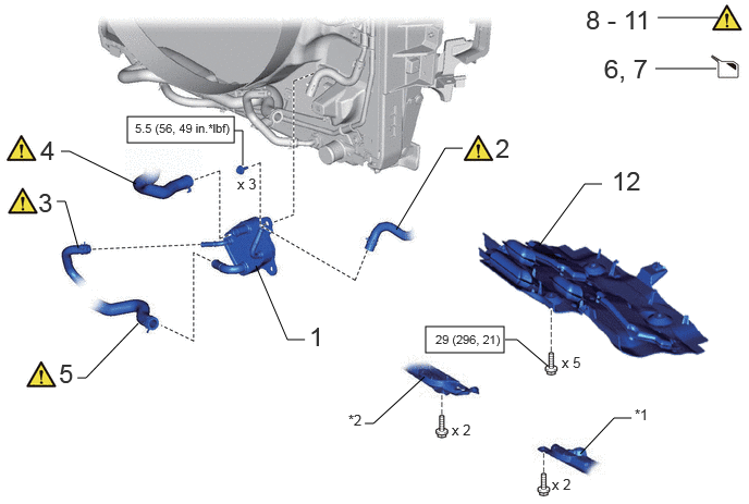
| Procedure | Part Name Code |

|

|

|
|
|---|---|---|---|---|---|
| 1 | OIL COOLER ASSEMBLY | 32910 | - | - | - |
| 2 | NO. 1 TRANSMISSION OIL COOLER HOSE | 32943 | ( ) |
- | - |
| 3 | NO. 3 TRANSMISSION OIL COOLER HOSE | 32943C | () |
- | - |
| 4 | NO. 3 WATER BY-PASS HOSE | 16267C | () |
- | - |
| 5 | NO. 4 WATER BY-PASS HOSE | 16281N | () |
- | - |
| 6 | ADD ENGINE COOLANT | - | - | () |
- |
| 7 | ADD AND ADJUST AUTOMATIC TRANSMISSION FLUID | - | - | () |
- |
| 8 | INSPECT FOR COOLANT LEAK | - | () |
- | - |
| 9 | AFTER FILLING AUTOMATIC TRANSMISSION | - | () |
- | - |
| 10 | ATF THERMAL DEGRADATION ESTIMATE RESET | - | () |
- | - |
| 11 | NO. 1 ENGINE UNDER COVER ASSEMBLY | 51410 | - | - | - |
| *1 | ENGINE SIDE COVER SUB-ASSEMBLY LH | *2 | ENGINE SIDE COVER SUB-ASSEMBLY RH |

|
N*m (kgf*cm, ft.*lbf): Specified torque | - | - |
PROCEDURE

 32910 1.INSTALL OIL COOLER ASSEMBLY
- Torque:
- 5.5 N*m (56 kgf*cm, 49 in.*lbf)
32943 2.CONNECT NO. 1 TRANSMISSION OIL COOLER HOSE
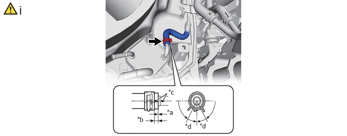
| *a | 0 to 3 mm (0 to 0.1181 in.) | *b | 2 to 7 mm (0.0787 to 0.275 in.) |
| *c | Paint Mark (Rear Side of Vehicle) | *d | 30° (Claw of Hose Clip Location) |
Connect the No. 1 transmission oil cooler hose to the oil cooler assembly and slide the hose clip to secure the hose.
- NOTICE:
-
·
Make sure to slide the No. 1 transmission oil cooler hose until it contacts the hose stopper of the oil cooler assembly.
·Make sure to align the paint mark of the No. 1 transmission oil cooler hose with the paint mark of the oil cooler assembly.
·Make sure that the claws of the hose clip are within the location shown in the illustration.
32943C 3.CONNECT NO. 3 TRANSMISSION OIL COOLER HOSE
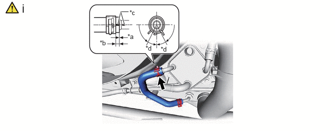
| *a | 0 to 3 mm (0 to 0.1181 in.) | *b | 2 to 7 mm (0.0787 to 0.275 in.) |
| *c | Paint Mark | *d | 30° (Claw of Hose Clip Location) |
Connect the No. 3 transmission oil cooler hose to the oil cooler assembly and slide the hose clip to secure the hose.
- NOTICE:
-
·
Make sure to slide the No. 3 transmission oil cooler hose until it contacts the hose stopper of the oil cooler assembly.
·Make sure to align the paint mark of the No. 3 transmission oil cooler hose with the paint mark of the oil cooler assembly.
·Make sure that the claws of the hose clip are within the location shown in the illustration.
16267C 4.CONNECT NO. 3 WATER BY-PASS HOSE
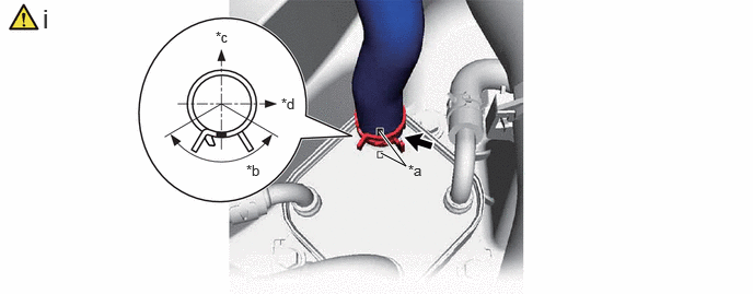
| *a | Paint Mark (Bottom Side of Vehicle) | *b | 120° (Claw of Hose Clip Location) |
| *c | Upper Side of Vehicle | *d | RH Side of Vehicle |
Connect the No. 3 water by-pass hose to the oil cooler assembly and slide the hose clip to secure the hose.
- NOTICE:
-
Make sure that the claws of the hose clip are within the location shown in the illustration.
16281N 5.CONNECT NO. 4 WATER BY-PASS HOSE
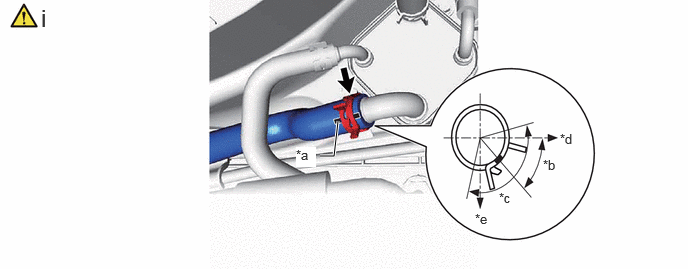
| *a | Paint Mark (Rear Side of Vehicle) | *b | 45° (Claw of Hose Clip Location) |
| *c | 120° (Claw of Hose Clip Location) | *d | Rear Side of Vehicle |
| *e | Bottom Side of Vehicle | - | - |
Connect the No. 4 water by-pass hose to the oil cooler assembly and slide the hose clip to secure the hose.
- NOTICE:
-
Make sure that the claws of the hose clip are within the location shown in the illustration.
6.ADD ENGINE COOLANT
7. ADD AND ADJUST AUTOMATIC TRANSMISSION FLUID
8.INSPECT FOR COOLANT LEAK
9. AFTER FILLING AUTOMATIC TRANSMISSION
10. ATF THERMAL DEGRADATION ESTIMATE RESET
51410 11.INSTALL NO. 1 ENGINE UNDER COVER ASSEMBLY