V35A-FTS ENGINE CONTROL CAMSHAFT POSITION SENSOR INSTALLATION
CAUTION / NOTICE / HINT
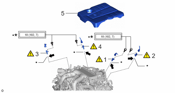
| Procedure | Part Name Code |

|

|

|
|
|---|---|---|---|---|---|
| 1 | CAMSHAFT POSITION SENSOR (for Exhaust Side of Bank 2) | 11101E | ( ) |
- | - |
| 2 | CAMSHAFT POSITION SENSOR (for Intake Side of Bank 2) | 11101E | () |
- | - |
| 3 | CAMSHAFT POSITION SENSOR (for Exhaust Side of Bank 1) | 11101E | () |
- | - |
| 4 | CAMSHAFT POSITION SENSOR (for Intake Side of Bank 1) | 11101E | () |
- | - |
| 5 | V-BANK COVER SUB-ASSEMBLY | 11209 | - | - | - |

|
Tightening torque for "Major areas involving basic vehicle performance such as moving/turning/stopping": N*m (kgf*cm, ft.*lbf) | ● | Non-reusable part |

|
Engine oil | ★ | Precoated part |
CAUTION / NOTICE / HINT
- NOTICE:
-
This procedure includes the installation of small-head bolts. Refer to Small-Head Bolts of Basic Repair Hint to identify the small-head bolts.
-
Click hereGeneral>INTRODUCTION>REPAIR INSTRUCTION>PRECAUTION
PROCEDURE

 11101E 1.INSTALL CAMSHAFT POSITION SENSOR (for Exhaust Side of Bank 2)
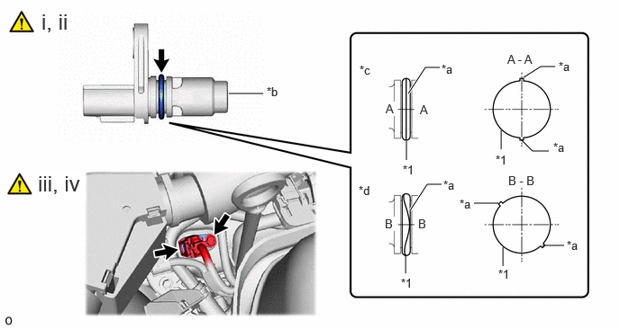
| *1 | O-ring | - | - |
| *a | Seam | *b | Camshaft Position Sensor Tip |
| *c | Correct | *d | Incorrect |
Perform this procedure only when reusing the camshaft position sensor (for Exhaust Side of Bank 2).
1. Clean the O-ring groove of the camshaft position sensor (for Exhaust Side of Bank 2).
- NOTICE:
-
Make sure the O-ring groove is free of foreign matter.
2. Install a new O-ring to the camshaft position sensor (for Exhaust Side of Bank 2).
- NOTICE:
-
Set the O-ring on the tip of the camshaft position sensor (for Exhaust Side of Bank 2) and roll it into the O-ring groove with bare hands to install it.
3. Check if the O-ring is twisted.
- HINT:
-
Check the entire circumference of the seam of the O-ring for twisting.
Apply a light coat of engine oil to the O-ring of the camshaft position sensor (for Exhaust Side of Bank 2).
Install the camshaft position sensor (for Exhaust Side of Bank 2) with a new bolt.
- Torque:
- 10 N*m (102 kgf*cm, 7 ft.*lbf)
- NOTICE:
-
·
If the camshaft position sensor (for Exhaust Side of Bank 2) has been struck or dropped, replace it.
·Make sure that the O-ring is not cracked or moved out of place when installing the camshaft position sensor (for Exhaust Side of Bank 2).
Connect the camshaft position sensor (for Exhaust Side of Bank 2) connector.
11101E 2.INSTALL CAMSHAFT POSITION SENSOR (for Intake Side of Bank 2)
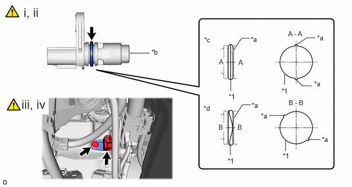
| *1 | O-ring | - | - |
| *a | Seam | *b | Camshaft Position Sensor Tip |
| *c | Correct | *d | Incorrect |
Perform this procedure only when reusing the camshaft position sensor (for Intake Side of Bank 2).
1. Clean the O-ring groove of the camshaft position sensor (for Intake Side of Bank 2).
- NOTICE:
-
Make sure the O-ring groove is free of foreign matter.
2. Install a new O-ring to the camshaft position sensor (for Intake Side of Bank 2).
- NOTICE:
-
Set the O-ring on the tip of the camshaft position sensor (for Intake Side of Bank 2) and roll it into the O-ring groove with bare hands to install it.
3. Check if the O-ring is twisted.
- HINT:
-
Check the entire circumference of the seam of the O-ring for twisting.
Apply a light coat of engine oil to the O-ring of the camshaft position sensor (for Intake Side of Bank 2).
Install the camshaft position sensor (for Intake Side of Bank 2) with a new bolt.
- Torque:
- 10 N*m (102 kgf*cm, 89 in.*lbf)
- NOTICE:
-
·
If the camshaft position sensor (for Intake Side of Bank 2) has been struck or dropped, replace it.
·Make sure that the O-ring is not cracked or moved out of place when installing the camshaft position sensor (for Intake Side of Bank 2).
Connect the camshaft position sensor (for Intake Side of Bank 2) connector.
11101E 3.INSTALL CAMSHAFT POSITION SENSOR (for Exhaust Side of Bank 1)
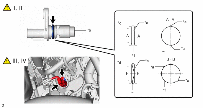
| *1 | O-ring | - | - |
| *a | Seam | *b | Camshaft Position Sensor Tip |
| *c | Correct | *d | Incorrect |
Perform this procedure only when reusing the camshaft position sensor (for Exhaust Side of Bank 1).
1. Clean the O-ring groove of the camshaft position sensor (for Exhaust Side of Bank 1).
- NOTICE:
-
Make sure the O-ring groove is free of foreign matter.
2. Install a new O-ring to the camshaft position sensor (for Exhaust Side of Bank 1).
- NOTICE:
-
Set the O-ring on the tip of the camshaft position sensor (for Exhaust Side of Bank 1) and roll it into the O-ring groove with bare hands to install it.
3. Check if the O-ring is twisted.
- HINT:
-
Check the entire circumference of the seam of the O-ring for twisting.
Apply a light coat of engine oil to the O-ring of the camshaft position sensor (for Exhaust Side of Bank 1).
Install the camshaft position sensor (for Exhaust Side of Bank 1) with a new bolt.
- Torque:
- 10 N*m (102 kgf*cm, 89 in.*lbf)
- NOTICE:
-
·
If the camshaft position sensor (for Exhaust Side of Bank 1) has been struck or dropped, replace it.
·Make sure that the O-ring is not cracked or moved out of place when installing the camshaft position sensor (for Exhaust Side of Bank 1).
Connect the camshaft position sensor (for Exhaust Side of Bank 1) connector.
11101E 4.INSTALL CAMSHAFT POSITION SENSOR (for Intake Side of Bank 1)
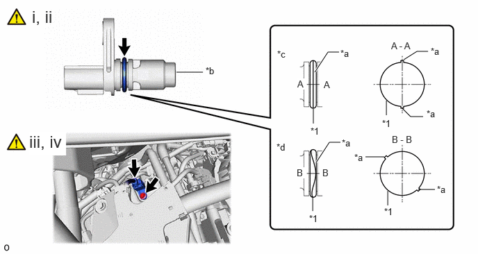
| *1 | O-ring | - | - |
| *a | Seam | *b | Camshaft Position Sensor Tip |
| *c | Correct | *d | Incorrect |
Perform this procedure only when reusing the camshaft position sensor (for Intake Side of Bank 1).
1. Clean the O-ring groove of the camshaft position sensor (for Intake Side of Bank 1).
- NOTICE:
-
Make sure the O-ring groove is free of foreign matter.
2. Install a new O-ring to the camshaft position sensor (for Intake Side of Bank 1).
- NOTICE:
-
Set the O-ring on the tip of the camshaft position sensor (for Intake Side of Bank 1) and roll it into the O-ring groove with bare hands to install it.
3. Check if the O-ring is twisted.
- HINT:
-
Check the entire circumference of the seam of the O-ring for twisting.
Apply a light coat of engine oil to the O-ring of the camshaft position sensor (for Intake Side of Bank 1).
Install the camshaft position sensor (for Intake Side of Bank 1) with a new bolt.
- Torque:
- 10 N*m (102 kgf*cm, 89 in.*lbf)
- NOTICE:
-
·
If the camshaft position sensor (for Intake Side of Bank 1) has been struck or dropped, replace it.
·Make sure that the O-ring is not cracked or moved out of place when installing the camshaft position sensor (for Intake Side of Bank 1).
Connect the camshaft position sensor (for Intake Side of Bank 1) connector.
11209 5.INSTALL V-BANK COVER SUB-ASSEMBLY