Home › Engine / Hybrid System › 1GR-FE (ENGINE CONTROL) › THROTTLE BODY
RM38G0E _51 Engine / Hybrid System _100527 1GR-FE ENGINE CONTROL _0467380 THROTTLE BODY A

1GR-FE ENGINE CONTROL  THROTTLE BODY  INSTALLATION  


CAUTION / NOTICE / HINT
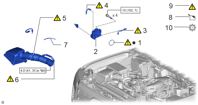
COMPONENTS (INSTALLATION)
A489132N03
4.375,0.26 5.063,0.479 0.688,0.219 0.708,2.469 1.667,2.656 0.958,0.188 6.344,0.604 6.854,0.604 false 0.76,2.865 1.958,2.865 1.958,2.865 1.958,2.24 true 1.667,2.552 1.823,2.552 1.823,2.552 1.823,2.406 true 6.344,0.198 6.854,0.198 false 6.302,0.979 6.813,0.979 false 4.469,1.104 4.833,1.104 true 4.135,1.542 4.5,1.542 false 3.885,0.51 3.885,0.365 3.885,0.365 4.365,0.365 true 3.469,0.177 3.146,0.177 3.146,0.177 3.146,0.354 true 1.208,1.99 1.458,0.635 1.458,0.635 1.938,0.635 true 2.208,1.625 1.938,1.625 1.938,1.625 1.813,1.375 true 3.469,1.354 3.469,1.698 false 4.99,1.396 5.271,1.75 0.281,0.354 18 false 1 3.396,1.719 3.677,2.073 0.281,0.354 18 false 2 5.177,0.958 5.458,1.313 0.281,0.354 18 false 3 3.781,0.042 4.063,0.396 0.281,0.354 18 false 4 0.542,2.74 0.823,3.094 0.281,0.354 18 false 6 2.313,1.479 2.594,1.833 0.281,0.354 18 false 7 6.104,0.479 6.385,0.833 0.281,0.354 18 false 8 6.115,0.063 6.396,0.417 0.281,0.354 18 false 9 5.969,0.854 6.385,1.188 0.417,0.333 18 false 10 4.417,0.302 5.094,0.5 0.677,0.198 8 false 10 (102, 7) 4.073,0.469 4.75,0.667 0.677,0.198 10 false x 4 4.771,1.385 5.24,1.677 0.469,0.292 18 false ● 0.74,2.49 1.781,2.677 1.042,0.188 8 false 4.0 (41, 35 in.*lbf) 2.26,0.51 2.542,0.865 0.281,0.354 18 false 5

Procedure Part Name Code
Z101186

Z101188

Z101187

1 THROTTLE BODY GASKET 22271 (Click here) - -
2 THROTTLE WITH THROTTLE POSITION SENSOR BODY ASSEMBLY 22030 - - -
3 NO. 4 WATER BY-PASS HOSE 16281 (Click here) - -
4 NO. 5 WATER BY-PASS HOSE 16282 (Click here) - -
5 AIR CLEANER CAP WITH AIR CLEANER HOSE 17735 (Click here) - -
6 NO. 2 VENTILATION HOSE 12262 (Click here) - -
7 VACUUM TRANSMITTING HOSE ASSEMBLY 25760 - - -
8 ADD ENGINE COOLANT - - (Click here) -
9 INSPECT FOR COOLANT LEAK - (Click here) - -
10 PERFORM INITIALIZATION - - - (Click here)

V100146

N*m (kgf*cm, ft.*lbf): Specified torque ● Non-reusable part

PROCEDURE

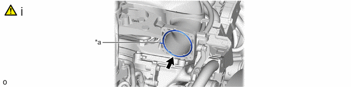
Hide 22271 1.INSTALL THROTTLE BODY GASKET
a.
A489136C01
2.094,0.875 3.24,0.875 true 1.938,0.781 2.25,0.979 0.313,0.198 10 false *a 0.417,0.083 0.698,0.438 0.281,0.354 18 false i
*a Protrusion - -


i.

Install a new throttle body gasket to the intake air surge tank with the protrusion of the throttle body gasket oriented as shown in the illustration.


Hide 22030 2.INSTALL THROTTLE WITH THROTTLE POSITION SENSOR BODY ASSEMBLY

Torque:
10 N*m (102 kgf*cm, 7 ft.*lbf)

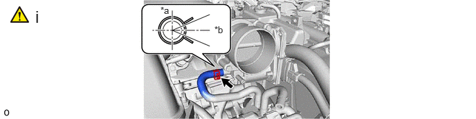
Hide 16281 3.CONNECT NO. 4 WATER BY-PASS HOSE
a.
A486886C01
0.531,0.104 0.719,0.573 0.188,0.469 18 false i 3.229,0.365 3.458,0.552 0.229,0.188 10 false *b 2.417,0.073 2.646,0.26 0.229,0.188 10 false *a
*a Upper Side *b RH Side


i.

Connect the No. 4 water by-pass hose to the throttle with throttle position sensor body assembly and slide the clip to secure it.

NOTICE:

Make sure to position the clip as shown in the illustration.


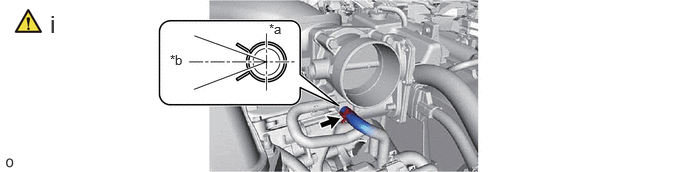
Hide 16282 4.CONNECT NO. 5 WATER BY-PASS HOSE
a.
A486887C01
1.771,0.542 2.083,0.74 0.313,0.198 10 false *b 2.802,0.219 3.115,0.417 0.313,0.198 10 false *a 0.521,0.104 0.74,0.646 0.219,0.542 18 false i
*a Upper Side *b Rear Side


i.

Connect the No. 5 water by-pass hose to the throttle with throttle position sensor body assembly and slide the clip to secure it.

NOTICE:

Make sure to position the clip as shown in the illustration.


Hide 17735 5.INSTALL AIR CLEANER CAP WITH AIR CLEANER HOSE
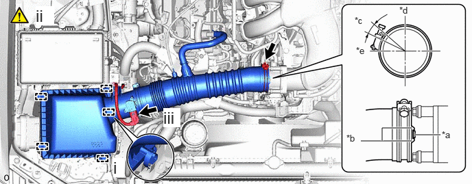
a.
A486888C01
6.302,2.052 6.688,2.052 true 5.479,2.146 6.25,2.146 true 5.802,2.146 5.802,1.948 5.802,1.948 6.25,1.948 true 6.708,1.969 7.021,2.125 0.313,0.156 10 false *a 5.26,2.021 5.573,2.177 0.313,0.156 10 false *b 5.385,0.229 5.698,0.385 0.313,0.156 10 false *c 5.406,0.688 5.719,0.844 0.313,0.156 10 false *e 6.063,0.073 6.375,0.229 0.313,0.156 10 false *d 0.542,0.094 0.823,0.385 0.281,0.292 18 true ii 1.719,2.406 1.885,2.698 0.167,0.292 18 true i 2.479,1.646 2.74,1.938 0.26,0.292 18 true iii
*a Protrusion *b Cutout
*c 15° *d Upper Side
*e Rear Side - -


i.

Attach the 4 clamps and install the air cleaner cap sub-assembly with air cleaner hose.


ii.

Tighten the hose clamp in the position shown in the illustration.

Torque:
4.0 N*m (41 kgf*cm, 35 in.*lbf)

NOTICE:

Make sure that the end of the hose clamp is positioned as shown in the illustration.


iii.

Attach the clamp and connect the intake mass air flow meter connector.


Hide 12262 6.CONNECT NO. 2 VENTILATION HOSE
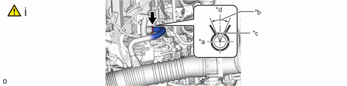
a.
A486889C01
4.552,0.688 5.167,0.688 true 4.583,0.406 4.969,0.24 4.969,0.24 5.25,0.24 true 4.104,0.781 4.417,0.979 0.313,0.198 10 false *a 5.26,0.167 5.573,0.365 0.313,0.198 10 false *b 5.219,0.604 5.531,0.802 0.313,0.198 10 false *c 4.458,0.115 4.771,0.313 0.313,0.198 10 false *d 0.5,0.094 0.781,0.448 0.281,0.354 18 false i
*a FR Side *b 45° (Claw of Clip Location)
*c Paint *d Upper Side


i.

Connect the No. 2 ventilation hose to the cylinder head cover sub-assembly and slide the clip to secure it.

NOTICE:

Make sure to position the clip as shown in the illustration.


Hide 25760 7.CONNECT VACUUM TRANSMITTING HOSE ASSEMBLY

Hide 8.ADD ENGINE COOLANT

Hide 9.INSPECT FOR COOLANT LEAK