1GR-FE ENGINE CONTROL AIR FUEL RATIO SENSOR INSTALLATION
CAUTION / NOTICE / HINT
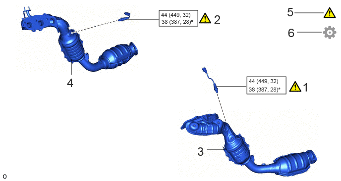
| Procedure | Part Name Code |

|

|

|
|
|---|---|---|---|---|---|
| 1 | AIR FUEL RATIO SENSOR (for Bank 2) | 89467B | ( ) |
- | - |
| 2 | AIR FUEL RATIO SENSOR (for Bank 1) | 89467B | () |
- | - |
| 3 | EXHAUST MANIFOLD ASSEMBLY LH | 17150 | - | - | - |
| 4 | EXHAUST MANIFOLD ASSEMBLY RH | 17140 | - | - | - |
| 5 | INSPECT FOR EXHAUST GAS LEAK | - | () |
- | - |
| 6 | PERFORM INITIALIZATION | - | - | - | () |

|
N*m (kgf*cm, ft.*lbf): Specified torque | * | For use with SST |
PROCEDURE

 89467B 1.INSTALL AIR FUEL RATIO SENSOR (for Bank 2)
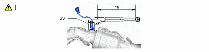
| *a | Torque Wrench Fulcrum Length | - | - |
Using SST, install the air fuel ratio sensor to the exhaust manifold.
- SST
-
09224-00012
- Torque:
- Specified tightening torque : 44 N*m (449 kgf*cm, 32 ft.*lbf)
- NOTICE:
-
Do not damage the air fuel ratio sensor.
- HINT:
-
·
Calculate the torque wrench reading when changing the fulcrum length of the torque wrench.
Click hereGeneral>INTRODUCTION>REPAIR INSTRUCTION>PRECAUTION
·When using SST (fulcrum length of 30 mm (1.18 in.)) + torque wrench (fulcrum length of 180 mm (7.09 in.)): 37.7 N*m (384 kgf*cm, 28 ft.*lbf)
89467B 2.INSTALL AIR FUEL RATIO SENSOR (for Bank 1)
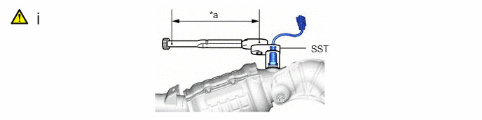
| *a | Torque Wrench Fulcrum Length | - | - |
Using SST, install the air fuel ratio sensor to the exhaust manifold.
- SST
-
09224-00012
- Torque:
- Specified tightening torque : 44 N*m (449 kgf*cm, 32 ft.*lbf)
- NOTICE:
-
Do not damage the air fuel ratio sensor.
- HINT:
-
·
Calculate the torque wrench reading when changing the fulcrum length of the torque wrench.
Click hereGeneral>INTRODUCTION>REPAIR INSTRUCTION>PRECAUTION
·When using SST (fulcrum length of 30 mm (1.18 in.)) + torque wrench (fulcrum length of 180 mm (7.09 in.)): 37.7 N*m (384 kgf*cm, 28 ft.*lbf)
17150 3.INSTALL EXHAUST MANIFOLD ASSEMBLY LH
17140 4.INSTALL EXHAUST MANIFOLD ASSEMBLY RH
5.INSPECT FOR EXHAUST GAS LEAK
6.PERFORM INITIALIZATION
Perform "Inspection After Repair" after replacing the air fuel ratio sensor.
Click hereEngine / Hybrid System>1GR-FE (ENGINE CONTROL)>SFI SYSTEM>INITIALIZATION