1GR-FE INTAKE / EXHAUST EXHAUST MANIFOLD INSTALLATION
CAUTION / NOTICE / HINT
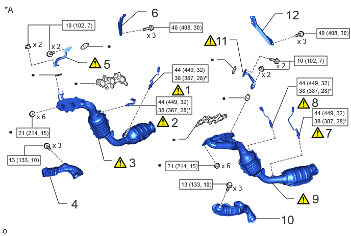
| Procedure | Part Name Code |

|

|

|
|
|---|---|---|---|---|---|
| 1 | HEATED OXYGEN SENSOR (for Bank 1) | 89465 | ( ) |
- | - |
| 2 | AIR FUEL RATIO SENSOR (for Bank 1) | 89467B | () |
- | - |
| 3 | EXHAUST MANIFOLD ASSEMBLY RH | 17140 | () |
- | - |
| 4 | NO. 1 EXHAUST MANIFOLD HEAT INSULATOR | 17167 | - | - | - |
| 5 | AIR TUBE | 17361 | () |
- | - |
| 6 | MANIFOLD STAY | 17118 | - | - | - |
| 7 | HEATED OXYGEN SENSOR (for Bank 2) | 89465A | () |
- | - |
| 8 | AIR FUEL RATIO SENSOR (for Bank 2) | 89467B | () |
- | - |
| 9 | EXHAUST MANIFOLD ASSEMBLY LH | 17150 | () |
- | - |
| 10 | NO. 2 EXHAUST MANIFOLD HEAT INSULATOR | 17168 | - | - | - |
| 11 | NO. 2 AIR TUBE | 17362 | () |
- | - |
| 12 | NO. 2 MANIFOLD STAY | 17119 | - | - | - |
| *A | w/ Secondary Air Injection System | - | - |

|
N*m (kgf*cm, ft.*lbf): Specified torque | * | For use with SST |
| ● | Non-reusable part | - | - |
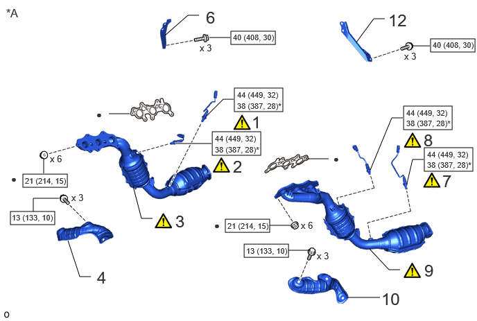
| Procedure | Part Name Code |
|
|
|
|
|---|---|---|---|---|---|
| 1 | HEATED OXYGEN SENSOR (for Bank 1) | 89465 | () |
- | - |
| 2 | AIR FUEL RATIO SENSOR (for Bank 1) | 89467B | () |
- | - |
| 3 | EXHAUST MANIFOLD ASSEMBLY RH | 17140 | () |
- | - |
| 4 | NO. 1 EXHAUST MANIFOLD HEAT INSULATOR | 17167 | - | - | - |
| 6 | MANIFOLD STAY | 17118 | - | - | - |
| 7 | HEATED OXYGEN SENSOR (for Bank 2) | 89465A | () |
- | - |
| 8 | AIR FUEL RATIO SENSOR (for Bank 2) | 89467B | () |
- | - |
| 9 | EXHAUST MANIFOLD ASSEMBLY LH | 17150 | () |
- | - |
| 10 | NO. 2 EXHAUST MANIFOLD HEAT INSULATOR | 17168 | - | - | - |
| 12 | NO. 2 MANIFOLD STAY | 17119 | - | - | - |
| *A | w/o Secondary Air Injection System | - | - |
|
|
N*m (kgf*cm, ft.*lbf): Specified torque | * | For use with SST |
| ● | Non-reusable part | - | - |
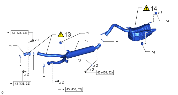
| Procedure | Part Name Code |
|
|
|
|
|---|---|---|---|---|---|
| 13 | FRONT AND CENTER EXHAUST PIPE ASSEMBLY | - | () |
- | - |
| 14 | TAIL EXHAUST PIPE ASSEMBLY | 17430 | () |
- | - |
| *1 | FRONT EXHAUST PIPE ASSEMBLY | *2 | CENTER EXHAUST PIPE ASSEMBLY |
| *3 | COMPRESSION SPRING | *4 | EXHAUST PIPE SUPPORT |
|
|
N*m (kgf*cm, ft.*lbf): Specified torque | ● | Non-reusable part |
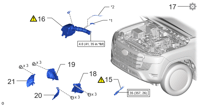
| Procedure | Part Name Code |
|
|
|
|
|---|---|---|---|---|---|
| 15 | NO. 2 STEERING INTERMEDIATE SHAFT SUB-ASSEMBLY | 45203 | () |
- | - |
| 16 | AIR CLEANER ASSEMBLY WITH AIR CLEANER HOSE ASSEMBLY | 17700 | () |
- | - |
| 17 | INSPECT FOR EXHAUST GAS LEAK | - | - | - | () |
| 18 | FRONT FENDER APRON TRIM PACKING D | 53785B | - | - | - |
| 19 | FRONT FENDER APRON TRIM PACKING C | 53784 | - | - | - |
| 20 | FRONT FENDER APRON TRIM PACKING B | 53783 | - | - | - |
| 21 | FRONT FENDER APRON TRIM PACKING A | 53782 | - | - | - |
| *1 | VENTILATION HOSE | *2 | VACUUM HOSE |

|
Tightening torque for "Major areas involving basic vehicle performance such as moving/turning/stopping": N*m (kgf*cm, ft.*lbf) |
|
N*m (kgf*cm, ft.*lbf): Specified torque |
PROCEDURE

 89465 1.INSTALL HEATED OXYGEN SENSOR (for Bank 1)
|
|
Click here() |
89467B 2.INSTALL AIR FUEL RATIO SENSOR (for Bank 1)
|
|
Click here() |
17140 3.INSTALL EXHAUST MANIFOLD ASSEMBLY RH
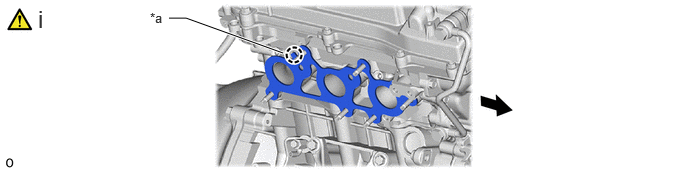
| *a | Rib | - | - |

|
Front | - | - |
Install a new gasket to the cylinder head sub-assembly.
- NOTICE:
-
Make sure the gasket is installed facing the proper direction.
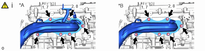
| *A | w/ Secondary Air Injection System | *B | w/o Secondary Air Injection System |
Install the exhaust manifold assembly RH with 6 new nuts in the order shown in the illustration.
- Torque:
- 21 N*m (214 kgf*cm, 15 ft.*lbf)
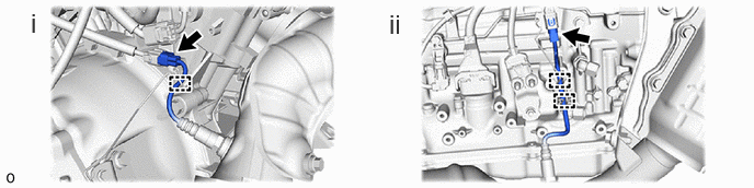
Connect the air fuel ratio sensor connector and attach the clamp.
Connect the heated oxygen sensor connector and attach the 2 clamps.
17167 4.INSTALL NO. 1 EXHAUST MANIFOLD HEAT INSULATOR
- Torque:
- 13 N*m (133 kgf*cm, 10 ft.*lbf)
17361 5.INSTALL AIR TUBE (w/ Secondary Air Injection System)
|
|
Click here() |
17118 6.INSTALL MANIFOLD STAY
- Torque:
- 40 N*m (408 kgf*cm, 30 ft.*lbf)
89465A 7.INSTALL HEATED OXYGEN SENSOR (for Bank 2)
|
|
Click here() |
89467B 8.INSTALL AIR FUEL RATIO SENSOR (for Bank 2)
|
|
Click here() |
17150 9.INSTALL EXHAUST MANIFOLD ASSEMBLY LH
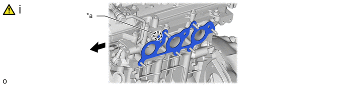
| *a | Rib | - | - |
|
|
Front | - | - |
Install a new gasket to the cylinder head LH.
- NOTICE:
-
Make sure the gasket is installed facing the proper direction.
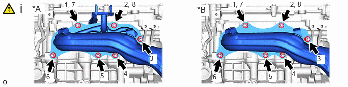
| *A | w/ Secondary Air Injection System | *B | w/o Secondary Air Injection System |
Install the exhaust manifold assembly LH with 6 new nuts in the order shown in the illustration.
- Torque:
- 21 N*m (214 kgf*cm, 15 ft.*lbf)
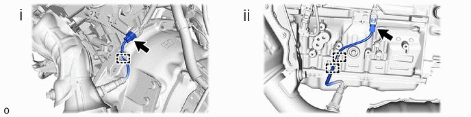
Connect the air fuel ratio sensor connector and attach the clamp.
Connect the heated oxygen sensor connector and attach the 2 clamps.
17168 10.INSTALL NO. 2 EXHAUST MANIFOLD HEAT INSULATOR
- Torque:
- 13 N*m (133 kgf*cm, 10 ft.*lbf)
17362 11.INSTALL NO. 2 AIR TUBE (w/ Secondary Air Injection System)
|
|
Click here() |
17119 12.INSTALL NO. 2 MANIFOLD STAY
- Torque:
- 40 N*m (408 kgf*cm, 30 ft.*lbf)
13.INSTALL FRONT AND CENTER EXHAUST PIPE ASSEMBLY
|
|
Click here() |
17430 14.INSTALL TAIL EXHAUST PIPE ASSEMBLY
|
|
Click here() |
45203 15.CONNECT NO. 2 STEERING INTERMEDIATE SHAFT SUB-ASSEMBLY
|
|
Click here() |
17700 16.INSTALL AIR CLEANER ASSEMBLY WITH AIR CLEANER HOSE ASSEMBLY
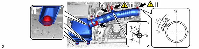
| *a | Upper Side | *b | RH Side |
| *c | Rear Side | *d | 180° |
| *e | 15° | *f | 45° |
Attach the 3 grommets to install the air cleaner assembly with air cleaner hose assembly.
Connect the air cleaner hose and tighten the hose clamp.
- Torque:
- 4.0 N*m (41 kgf*cm, 35 in.*lbf)
- NOTICE:
-
Align the hose clamp at the locations shown in the illustration.
Connect the ventilation hose and slide the hose clip to secure it.
- NOTICE:
-
Align the hose clip at the locations shown in the illustration.
Connect the vacuum hose.
Attach the clamp and connect the connector.
17.INSPECT FOR EXHAUST GAS LEAK
53785B 18.INSTALL FRONT FENDER APRON TRIM PACKING D
53784 19.INSTALL FRONT FENDER APRON TRIM PACKING C
53783 20.INSTALL FRONT FENDER APRON TRIM PACKING B
53782 21.INSTALL FRONT FENDER APRON TRIM PACKING A
22.PERFORM INITIALIZATION
Perform "Inspection After Repair" after replacing the air fuel ratio sensor.
Click hereEngine / Hybrid System>1GR-FE (ENGINE CONTROL)>SFI SYSTEM>INITIALIZATION