Home › General › MAINTENANCE › V35A-FTS DRIVE BELT
RM38G0E _V1 General _100461 MAINTENANCE _0467559 V35A-FTS DRIVE BELT A

MAINTENANCE  V35A-FTS DRIVE BELT  INSTALLATION  


CAUTION / NOTICE / HINT
COMPONENTS (INSTALLATION)
A485300N02
2.156,4.125 2.792,4.313 0.635,0.188 0.604,3.49 1.24,3.677 0.635,0.188 1.573,2.219 2.208,2.406 0.635,0.188 4.021,5.094 4.427,5.375 4.427,5.375 4.698,5.375 false 5.01,4.073 5.677,4.073 false 3.156,3.542 3.708,3.094 3.708,3.094 3.979,3.094 false 3.792,2.406 4.385,2.177 4.385,2.177 4.656,2.177 false 4.865,0.792 5.49,0.552 5.49,0.552 5.76,0.552 false 1.531,3 1.781,3 1.781,3 1.99,3.271 false 2.208,2.313 2.573,2.313 false 1.25,3.583 1.615,3.583 false 2.49,4.125 2.49,3.771 2.49,3.771 2.708,3.771 false 6.01,3.927 6.219,4.229 0.208,0.302 18 false 1 1.333,2.865 1.542,3.167 0.208,0.302 18 false 2 4.719,2.042 4.927,2.344 0.208,0.302 18 false 3 5.042,5.24 5.25,5.542 0.208,0.302 18 false 4 4.031,2.958 4.24,3.26 0.208,0.302 18 false 5 5.813,0.406 6.021,0.708 0.208,0.302 18 false 6 2.583,2.365 2.844,2.563 0.26,0.198 10 false x 2 1.635,3.646 1.896,3.844 0.26,0.198 10 false x 2 2.719,3.823 2.979,4.021 0.26,0.198 10 false x 2 2.188,4.135 2.813,4.313 0.625,0.177 8 false 10 (102, 7) 0.635,3.5 1.26,3.677 0.625,0.177 8 false 10 (102, 7) 1.604,2.229 2.229,2.406 0.625,0.177 8 false 10 (102, 7)

Procedure Part Name Code
Z101186

Z101188

Z101187

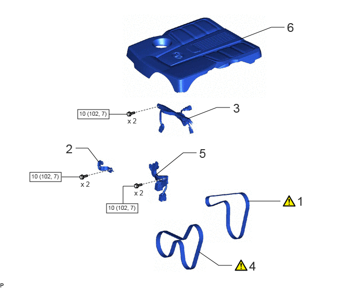
1 FAN AND GENERATOR V BELT 16361A (Click here) - -
2 NO. 1 AIR TUBE SUPPORT 17368G - - -
3 ENGINE WIRE 82121 - - -
4 NO. 1 V BELT (COOLER COMPRESSOR TO CRANKSHAFT PULLEY) 88310A (Click here) - -
5 COOLING FAN WIRE 16364A - - -
6 V-BANK COVER SUB-ASSEMBLY 11209 - - -

V100146

N*m (kgf*cm, ft.*lbf): Specified torque - -

A518234N07
4.76,2.771 5.458,2.948 0.698,0.177 5.365,1.583 5.729,1.135 5.729,1.135 5.948,1.135 true 1.563,1.938 1.771,1.938 1.771,1.938 1.979,1.521 true 3.938,2.969 3.719,2.969 3.719,2.969 3.552,2.542 true 4.75,2.854 4.531,2.854 4.531,2.854 4.365,2.427 true 6.01,1 6.354,1.406 0.344,0.406 18 false 7 4.448,2.313 4.729,2.667 0.281,0.354 10 false x 5 3.083,2.729 3.365,3.083 0.281,0.354 10 false x 2 2.344,2.083 2.625,2.438 0.281,0.354 10 false x 2 1.385,1.875 1.667,2.229 0.281,0.354 10 false *2 4.01,2.896 4.292,3.25 0.281,0.354 10 false *1 4.813,2.792 5.552,3.052 0.74,0.26 8 false 29 (296, 21)

Procedure Part Name Code
Z101186

Z101188

Z101187

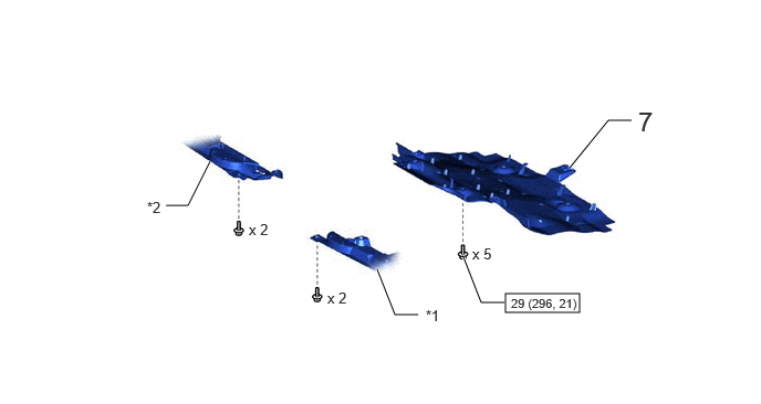
7 NO. 1 ENGINE UNDER COVER ASSEMBLY 51410 - - -

*1 ENGINE SIDE COVER SUB-ASSEMBLY LH *2 ENGINE SIDE COVER SUB-ASSEMBLY RH
V100146

N*m (kgf*cm, ft.*lbf): Specified torque - -

PROCEDURE

Hide 16361A 1.INSTALL FAN AND GENERATOR V BELT

Z101186

HINT:

When re-using the fan and generator V belt, check the entire circumference of the belt for wear and cracks on the ribs and rear side. Replace belts where wear and cracks have advanced to the wire core and belts with missing rib rubber.


a.
A518236C01
5.365,0.552 5.167,0.292 5.167,0.292 4.927,0.292 true 4.323,3.333 4.521,3.333 false 0.792,1.052 0.99,1.26 0.198,0.208 10 false *1 2.583,0.49 2.781,0.698 0.198,0.208 10 false *2 2.313,1.385 2.51,1.594 0.198,0.208 10 false *3 0.781,2.49 0.979,2.698 0.198,0.208 10 false *a 4.156,3.26 4.354,3.469 0.198,0.208 10 false *c 3.885,0.083 4.115,0.365 0.229,0.281 18 false ii 0.417,0.083 0.646,0.365 0.229,0.281 18 false i 0.427,2.01 0.656,2.292 0.229,0.281 18 false iii 4.719,0.229 4.906,0.417 0.188,0.188 10 true *4 2.385,2.479 2.583,2.688 0.198,0.208 10 false *b
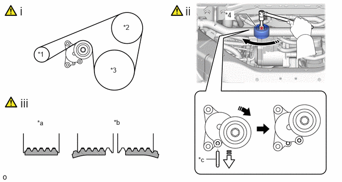
*1 Generator Assembly *2 Water Pump Assembly
*3 Crankshaft Pulley *4 V-ribbed Belt Tensioner Sub-assembly
*a Correct *b Incorrect
*c 5 mm Hexagon Wrench - -
V113147

Turn in this Direction
V113148

Remove the 5 mm hexagon wrench


i.

Set the fan and generator V belt onto each part.


ii.

Rotate the V-ribbed belt tensioner sub-assembly clockwise, and then remove the 5 mm hexagon wrench.

NOTICE:

Make sure that the fan and generator V belt is properly installed to each pulley.


iii.

Check that the belt fits properly in the ribbed grooves.


Hide 17368G 2.INSTALL NO. 1 AIR TUBE SUPPORT

Torque:
10 N*m (102 kgf*cm, 7 ft.*lbf)

Hide 82121 3.CONNECT ENGINE WIRE

Torque:
10 N*m (102 kgf*cm, 7 ft.*lbf)

Hide 88310A 4.INSTALL NO. 1 V BELT (COOLER COMPRESSOR TO CRANKSHAFT PULLEY)

Z101186

HINT:

When re-using the No. 1 V belt (cooler compressor to crankshaft pulley), check the entire circumference of the belt for wear and cracks on the ribs and rear side. Replace belts where wear and cracks have advanced to the wire core and belts with missing rib rubber.


a.
A518237C01
4.583,2.083 4.771,2.083 4.771,2.083 5,2.198 false 6.469,1.104 6.323,1.104 6.323,1.104 6,0.885 true 1.094,1.333 1.292,1.51 0.198,0.177 10 false *1 1.76,1.125 1.969,1.323 0.208,0.198 10 false *2 2.354,1.271 2.573,1.458 0.219,0.188 10 false *3 2.51,0.406 2.719,0.615 0.208,0.208 10 false *4 4.406,2.01 4.604,2.219 0.198,0.208 10 false *c 0.771,2.51 0.969,2.708 0.198,0.198 10 false *a 2.354,2.49 2.552,2.688 0.198,0.198 10 false *b 0.531,1.969 0.781,2.26 0.25,0.292 18 false iii 0.531,0.094 0.781,0.385 0.25,0.292 18 false i 3.865,0.094 4.115,0.385 0.25,0.292 18 false ii 6.5,1.021 6.698,1.229 0.198,0.208 10 true *5
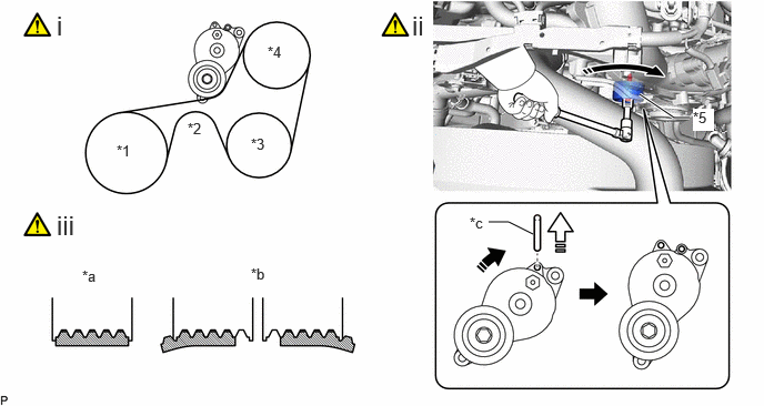
*1 Crankshaft Pulley *2 No. 2 Idler Pulley Sub-assembly
*3 Compressor Assembly with Pulley *4 Vane Pump Assembly
*5 No. 2 V-ribbed Belt Tensioner Assembly - -
*a Correct *b Incorrect
*c 5 mm Hexagon Wrench - -
V113147

Turn in this Direction
V113148

Remove the 5 mm hexagon wrench


i.

Set the No. 1 V belt (cooler compressor to crankshaft pulley) onto each part.


ii.

Rotate the No. 2 V-ribbed belt tensioner assembly clockwise, and then remove the 5 mm hexagon wrench.

NOTICE:

Make sure that the No. 1 V belt (cooler compressor to crankshaft pulley) is properly installed to each pulley.


iii.

Check that the belt fits properly in the ribbed grooves.


Hide 16364A 5.INSTALL COOLING FAN WIRE

Hide 11209 6.INSTALL V-BANK COVER SUB-ASSEMBLY

Hide 51410 7.INSTALL NO. 1 ENGINE UNDER COVER ASSEMBLY