METER / GAUGE / DISPLAY METER / GAUGE SYSTEM Voltage Meter Malfunction
DESCRIPTION
The voltmeter indicates the voltage applied to the IG+ terminal of the combination meter.
WIRING DIAGRAM
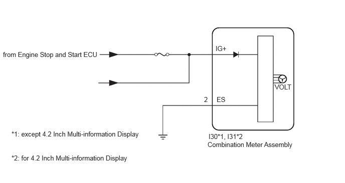
CAUTION / NOTICE / HINT
- NOTICE:
-
When replacing the combination meter assembly, always replace it with a new one. If a combination meter assembly which was installed to another vehicle is used, the information stored in it will not match the information from the vehicle and a DTC may be stored.
PROCEDURE
Check vehicle condition.
- Result:
-
Result Proceed to for 4.2 Inch Multi-information Display A for 7.0 Inch Multi-information Display B
A
B
Operate the GTS according to the display and select the Active Test.
Click hereVehicle Interior>METER / GAUGE / DISPLAY>METER / GAUGE SYSTEM>DATA LIST / ACTIVE TEST
- Body Electrical > Combination Meter > Active Test
-
Tester Display Measurement Item Control Range Diagnostic Note Volt Meter Operation (0V) Voltmeter (0 V) ON See [Display] Volt Meter Operation (3V) Voltmeter (3 V) ON See [Display] Volt Meter Operation (6V) Voltmeter (6 V) ON See [Display] Volt Meter Operation (9V) Voltmeter (9 V) ON See [Display] Volt Meter Operation (12V) Voltmeter (12 V) ON See [Display] Volt Meter Operation (15V) Voltmeter (15 V) ON See [Display] Volt Meter Operation (18V) Voltmeter (18 V) ON See [Display]
- Body Electrical > Combination Meter > Active Test
-
Tester Display Volt Meter Operation (0V) - 50004 409 244
- Body Electrical > Combination Meter > Active Test
-
Tester Display Volt Meter Operation (3V) - 50004 409 245
- Body Electrical > Combination Meter > Active Test
-
Tester Display Volt Meter Operation (6V) - 50004 409 246
- Body Electrical > Combination Meter > Active Test
-
Tester Display Volt Meter Operation (9V) - 50004 409 247
- Body Electrical > Combination Meter > Active Test
-
Tester Display Volt Meter Operation (12V) - 50004 409 248
- Body Electrical > Combination Meter > Active Test
-
Tester Display Volt Meter Operation (15V) - 50004 409 249
- Body Electrical > Combination Meter > Active Test
-
Tester Display Volt Meter Operation (18V) - 50004 409 250
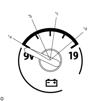
| *a | Volt Meter Operation (0V) Volt Meter Operation (3V) Volt Meter Operation (6V) Volt Meter Operation (9V) |
| *b | Volt Meter Operation (12V) |
| *c | Volt Meter Operation (15V) |
| *d | Volt Meter Operation (18V) |
[Display]: Voltage meter
- OK:
-
Voltage meter indication is normal.
- Result:
-
Proceed to OK NG
OK
NG
Disconnect the I5 combination meter assembly connector.
Measure the resistance and voltage according to the value(s) in the tables below.
- Standard Resistance:
-
Tester Connection Condition Specified Condition Click Location & Routing(I5)Location & Routingewd_type=routing;type=c;code=I5
I5-2 (ET) - Body ground Always Below 1 Ω
- Standard Voltage:
-
Tester Connection Switch Condition Specified Condition Click Location & Routing(I5)Location & Routingewd_type=routing;type=c;code=I5
I5-6 (IG+) - Body ground Ignition switch off Below 1 V Ignition switch ON 11 to 14 V*1
10.5 to 16 V*2
*1: w/o Stop and Start System
*2: w/ Stop and Start System
- Result:
-
Result Proceed to OK A NG (IG+ terminal) (w/ Stop and Start System) B NG (IG+ terminal) (w/o Stop and Start System) C NG (Other terminal)
A
B
Click hereEngine / Hybrid System>STOP AND START>STOP AND START SYSTEM>Backup Boost Converter Circuit
C
Disconnect the I5 combination meter assembly connector.
Measure the resistance and voltage according to the value(s) in the tables below.
- Standard Resistance:
-
Tester Connection Condition Specified Condition Click Location & Routing(I5)Location & Routingewd_type=routing;type=c;code=I5
I5-2 (ET) - Body ground Always Below 1 Ω
- Standard Voltage:
-
Tester Connection Switch Condition Specified Condition Click Location & Routing(I5)Location & Routingewd_type=routing;type=c;code=I5
I5-6 (IG+) - Body ground Ignition switch off Below 1 V Ignition switch ON 11 to 14 V*1
10.5 to 16 V*2
*1: w/o Stop and Start System
*2: w/ Stop and Start System
- Result:
-
Result Proceed to OK A NG (IG+ terminal) (w/ Stop and Start System) B NG (IG+ terminal) (w/o Stop and Start System) C NG (Other terminal)
A
B
Click hereEngine / Hybrid System>STOP AND START>STOP AND START SYSTEM>Backup Boost Converter Circuit
C