METER / GAUGE / DISPLAY COMBINATION METER REMOVAL
CAUTION / NOTICE / HINT
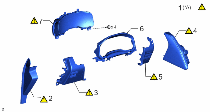
| Procedure | Part Name Code |

|

|

|
|
|---|---|---|---|---|---|
| 1 | CUSTOMIZE POWER TILT AND POWER TELESCOPIC STEERING COLUMN SYSTEM | - | ( ) |
- | - |
| 2 | NO. 2 INSTRUMENT SIDE PANEL | 55318F | () |
- | - |
| 3 | LOWER NO. 1 INSTRUMENT PANEL FINISH PANEL | 55432D | () |
- | - |
| 4 | INTEGRATION CONTROL AND PANEL SUB-ASSEMBLY | 84012 | () |
- | - |
| 5 | LOWER INSTRUMENT PANEL | 55312 | () |
- | - |
| 6 | INSTRUMENT CLUSTER FINISH PANEL SUB-ASSEMBLY | 55404D | - | - | - |
| 7 | COMBINATION METER ASSEMBLY | 83100 | () |
- | - |
| *A | for Power Tilt and Power Telescopic Steering Column | - | - |
- HINT:
-
·
Use the same procedure for RHD and LHD vehicles.
·The procedure listed below is for LHD vehicles.
PROCEDURE

 1. CUSTOMIZE POWER TILT AND POWER TELESCOPIC STEERING COLUMN SYSTEM (for Power Tilt and Power Telescopic Steering Column)
|
|
|
55318F 2.REMOVE NO. 2 INSTRUMENT SIDE PANEL
|
|
Click here() |
55432D 3.REMOVE LOWER NO. 1 INSTRUMENT PANEL FINISH PANEL
|
|
Click here() |
84012 4.REMOVE INTEGRATION CONTROL AND PANEL SUB-ASSEMBLY
|
|
Click here() |
55312 5.REMOVE LOWER INSTRUMENT PANEL
|
|
Click here() |
55404D 6.REMOVE INSTRUMENT CLUSTER FINISH PANEL SUB-ASSEMBLY
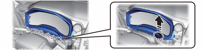

|
Place Hands Here |

|
Remove in this Direction |
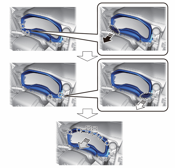
|
|
Place Hands Here |
|
Remove in this Direction (1) |

|
Remove in this Direction (2) |

|
Remove in this Direction (3) |

|
|
Remove in this Direction | - | - |
83100 7.REMOVE COMBINATION METER ASSEMBLY
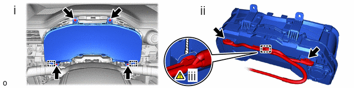
Remove the 4 screws.
Disconnect the 2 connectors.
Using a thin-bladed screwdriver, detach the clamp and remove the combination meter assembly.
- HINT:
-
Tape the thin-bladed screwdriver tip before use.

|
|
Remove in this Direction | - | - |