METER / GAUGE / DISPLAY HEADUP DISPLAY REMOVAL
CAUTION / NOTICE / HINT
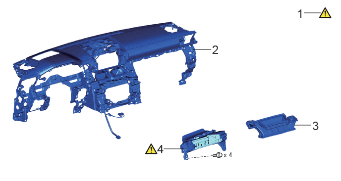
| Procedure | Part Name Code |

|

|

|
|
|---|---|---|---|---|---|
| 1 | PRECAUTION | - | ( ) |
- | - |
| 2 | INSTRUMENT PANEL SAFETY PAD ASSEMBLY | - | - | - | - |
| 3 | LOWER DEFROSTER NOZZLE ASSEMBLY | 55990B | - | - | - |
| 4 | METER MIRROR SUB-ASSEMBLY | 83108 | () |
- | - |
- HINT:
-
·
Use the same procedure for RHD and LHD vehicles.
·The procedure listed below is for LHD vehicles.
CAUTION / NOTICE / HINT
The necessary procedures (adjustment, calibration, initialization or registration) that must be performed after parts are removed and installed, or replaced during meter mirror sub-assembly removal/installation are shown below.
| Replaced Part or Performed Procedure | Necessary Procedures | Effect/Inoperative Function When Necessary Procedures are not Performed | Link |
|---|---|---|---|
| Disconnect cable from negative battery terminal | Memorize steering angle neutral point | Parking assist monitor system | () |
| Multi-terrain monitor system | () |
||
| Panoramic view monitor system | () |
- HINT:
-
·
When the cable is disconnected/reconnected to the battery terminal, systems temporarily stop operating. However, each system has a function that completes learning the first time the system is used.
-Learning completes when vehicle is driven
Effect/Inoperative Function When Necessary Procedures are not Performed Necessary Procedures Link Stop and start system Drive the vehicle until stop and start control is permitted (approximately 5 to 60 minutes). ( )Lighting system (EXT) Cornering lights Drive the vehicle straight ahead at 35 km/h (22 mph) or more for 5 second or more. ( )Pre-collision System Lane Tracing Assist System Lane departure alert system Adaptive high beam system
-Learning completes when vehicle is operated normally
Effect/Inoperative Function When Necessary Procedures are not Performed Necessary Procedures Link Power back door system Fully close the back door by hand.
- HINT:
-
Initialization is not necessary if the above procedures are performed while the back door is closed.
( )Air conditioning system After the ignition switch is turned to ON, the servo motor standard position is recognized. -
·Use the same procedure for RHD and LHD vehicles.
·The procedure listed below is for LHD vehicles.
PROCEDURE

 1. PRECAUTION
|
|
|
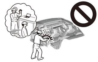
2.REMOVE INSTRUMENT PANEL SAFETY PAD ASSEMBLY
55990B 3.REMOVE LOWER DEFROSTER NOZZLE ASSEMBLY
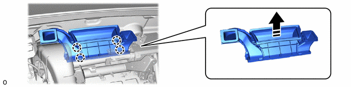

|
Remove in this Direction | - | - |
83108 4.REMOVE METER MIRROR SUB-ASSEMBLY
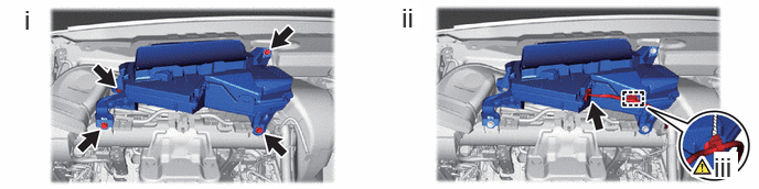
Remove the 4 bolts and meter mirror sub-assembly.
Disconnect the connector.
Using a thin-bladed screwdriver, detach the clamp.
- HINT:
-
Tape the thin-bladed screwdriver tip before use.