INTERIOR PANELS / TRIM INSTRUMENT PANEL SAFETY PAD REMOVAL
CAUTION / NOTICE / HINT
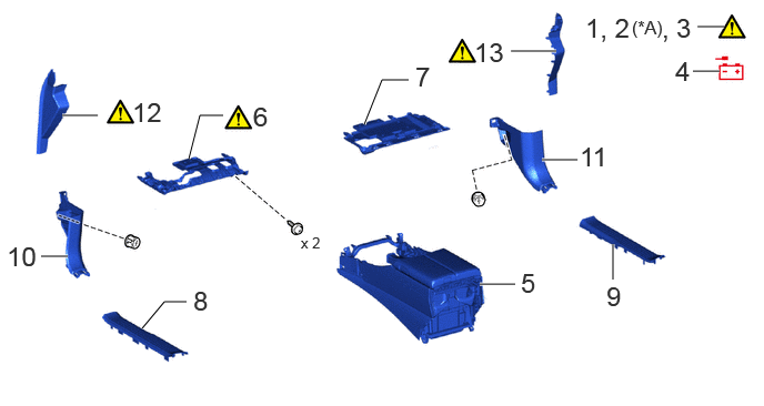
| Procedure | Part Name Code |

|

|

|
|
|---|---|---|---|---|---|
| 1 | PRECAUTION | - | ( ) |
- | - |
| 2 | CUSTOMIZE POWER TILT AND POWER TELESCOPIC STEERING COLUMN SYSTEM | - | () |
- | - |
| 3 | ALIGN FRONT WHEELS FACING STRAIGHT AHEAD | - | () |
- | - |
| 4 | DISCONNECT CABLE FROM NEGATIVE BATTERY TERMINAL | - | () |
- | - |
| 5 | FRONT CONSOLE BOX | - | - | - | - |
| 6 | NO. 1 INSTRUMENT PANEL UNDER COVER SUB-ASSEMBLY | 55606 | () |
- | - |
| 7 | NO. 2 INSTRUMENT PANEL UNDER COVER SUB-ASSEMBLY | 55607 | - | - | - |
| 8 | FRONT DOOR SCUFF PLATE LH | 67914B | - | - | - |
| 9 | FRONT DOOR SCUFF PLATE RH | 67913B | - | - | - |
| 10 | COWL SIDE TRIM BOARD LH | 62112 | - | - | - |
| 11 | COWL SIDE TRIM BOARD RH | 62111C | - | - | - |
| 12 | NO. 2 INSTRUMENT SIDE PANEL | 55318F | () |
- | - |
| 13 | NO. 1 INSTRUMENT SIDE PANEL | 55317E | () |
- | - |
| *A | for Power Tilt and Power Telescopic Steering Column | - | - |
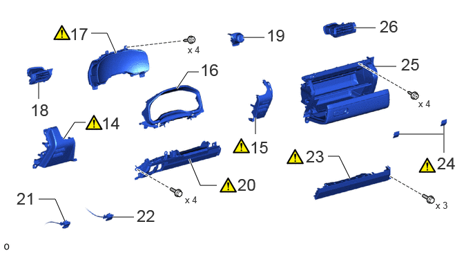
| Procedure | Part Name Code |
|
|
|
|
|---|---|---|---|---|---|
| 14 | LOWER NO. 1 INSTRUMENT PANEL FINISH PANEL | 55432D | () |
- | - |
| 15 | LOWER INSTRUMENT PANEL | 55312 | () |
- | - |
| 16 | INSTRUMENT CLUSTER FINISH PANEL SUB-ASSEMBLY | 55404D | - | - | - |
| 17 | COMBINATION METER ASSEMBLY | 83100 | () |
- | - |
| 18 | NO. 1 INSTRUMENT PANEL REGISTER ASSEMBLY | 55650 | - | - | - |
| 19 | NO. 1 SWITCH HOLE BASE | 55446A | - | - | - |
| 20 | LOWER NO. 1 INSTRUMENT PANEL AIRBAG ASSEMBLY | 73900 | () |
- | - |
| 21 | FUEL LID LOCK OPEN LEVER SUB-ASSEMBLY | 77306 | - | - | - |
| 22 | HOOD LOCK CONTROL LEVER SUB-ASSEMBLY | 53601 | - | - | - |
| 23 | LOWER NO. 2 INSTRUMENT PANEL AIRBAG ASSEMBLY | 73990 | () |
- | - |
| 24 | INSTRUMENT PANEL BOX DOOR COVER | 55443A | () |
- | - |
| 25 | LOWER NO. 2 INSTRUMENT PANEL ASSEMBLY | 55320 | - | - | - |
| 26 | NO. 2 INSTRUMENT PANEL REGISTER ASSEMBLY | 55660 | - | - | - |
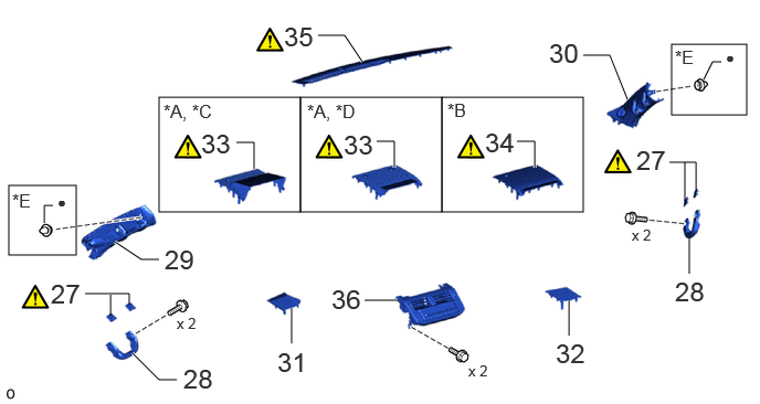
| Procedure | Part Name Code |
|
|
|
|
|---|---|---|---|---|---|
| 27 | ASSIST GRIP PLUG | 74617A | () |
- | - |
| 28 | FRONT ASSIST GRIP ASSEMBLY | 74620G | - | - | - |
| 29 | FRONT PILLAR GARNISH ASSEMBLY LH | 62212B | - | - | - |
| 30 | FRONT PILLAR GARNISH ASSEMBLY RH | 62211U | - | - | - |
| 31 | NO. 1 INSTRUMENT PANEL SPEAKER PANEL SUB-ASSEMBLY | 55408F | - | - | - |
| 32 | NO. 2 INSTRUMENT PANEL SPEAKER PANEL SUB-ASSEMBLY | 55409F | - | - | - |
| 33 | INSTRUMENT CLUSTER FINISH PANEL COVER | 55423B | () |
- | - |
| 34 | NO. 1 SPEAKER OPENING COVER ASSEMBLY | 55510F | () |
- | - |
| 35 | NO. 1 DEFROSTER NOZZLE GARNISH | 55981 | () |
- | - |
| 36 | AIR CONDITIONING PANEL ASSEMBLY | - | - | - | - |
| *A | w/o Multi-display | *B | w/ Multi-display |
| *C | for Type A | *D | for Type B |
| *E | w/ Curtain Shield Airbag | - | - |
| ● | Non-reusable part | - | - |
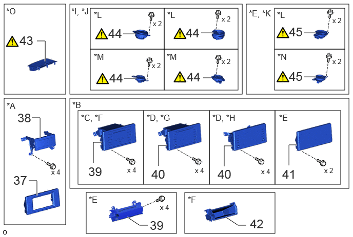
| Procedure | Part Name Code |
|
|
|
|
|---|---|---|---|---|---|
| 37 | CENTER UPPER INSTRUMENT CLUSTER FINISH PANEL | 55422C | - | - | - |
| 38 | RADIO TUNER OPENING COVER | 55522B | - | - | - |
| 39 | RADIO RECEIVER ASSEMBLY WITH BRACKET | - | - | - | - |
| 40 | RADIO AND DISPLAY RECEIVER ASSEMBLY WITH BRACKET | - | - | - | - |
| 41 | MULTI-DISPLAY ASSEMBLY | 86110B | - | - | - |
| 42 | CENTER LOWER INSTRUMENT CLUSTER FINISH PANEL SUB-ASSEMBLY | 55406B | - | - | - |
| 43 | INSTRUMENT CLUSTER FINISH PANEL END | 55414A | () |
- | - |
| 44 | FRONT NO. 3 SPEAKER ASSEMBLY | 86160J | () |
- | - |
| 45 | FRONT NO. 4 SPEAKER ASSEMBLY | 86160L | () |
- | - |
| *A | w/o Audio | *B | w/ Audio |
| *C | for Radio Receiver Type | *D | for Radio and Display Type |
| *E | w/ Multi-display | *F | w/o Multi-display |
| *G | for 7 Inch Display | *H | for 9 Inch Display |
| *I | except 2 Speakers | *J | for Side |
| *K | for Center | *L | for 10 Speakers |
| *M | except 10 Speakers | *N | for 14 Speakers |
| *O | w/ Headup Display | - | - |
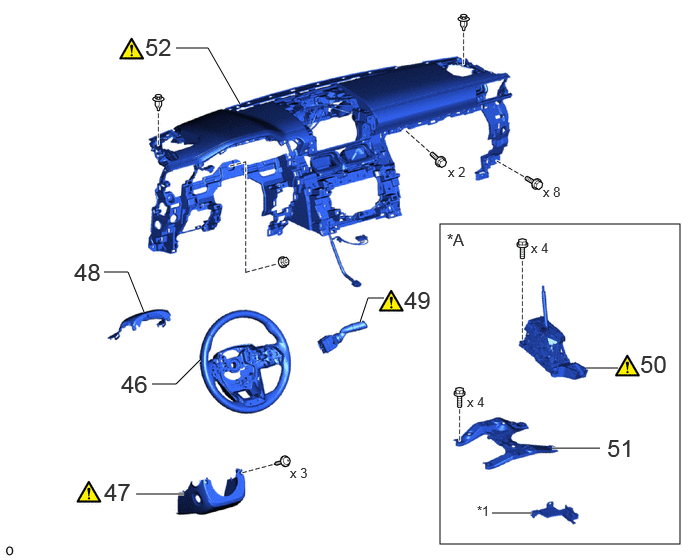
| Procedure | Part Name Code |
|
|
|
|
|---|---|---|---|---|---|
| 46 | STEERING WHEEL ASSEMBLY | 45100 | - | - | - |
| 47 | LOWER STEERING COLUMN COVER SUB-ASSEMBLY | 45024 | () |
- | - |
| 48 | UPPER STEERING COLUMN COVER | 45286B | - | - | - |
| 49 | WINDSHIELD WIPER SWITCH ASSEMBLY | 84650 | () |
- | - |
| 50 | FLOOR SHIFT LEVER ASSEMBLY | - | () |
- | - |
| 51 | SHIFT AND SELECT LEVER SUPPORT | 58123A | () |
- | - |
| 52 | INSTRUMENT PANEL SAFETY PAD ASSEMBLY | - | () |
- | - |
| *A | w/ Telematics Transceiver | - | - |
| *1 | WIRING HARNESS PROTECTOR | - | - |
CAUTION / NOTICE / HINT
The necessary procedures (adjustment, calibration, initialization or registration) that must be performed after parts are removed and installed, or replaced during instrument panel safety pad assembly removal/installation are shown below.
| Replaced Part or Performed Procedure | Necessary Procedures | Effect/Inoperative Function When Necessary Procedures are not Performed | Link |
|---|---|---|---|
| Disconnect cable from negative (-) battery terminal | Memorize steering angle neutral point | Parking assist monitor system | () |
| Multi-terrain monitor system | () |
||
| Panoramic view monitor system | () |
- HINT:
-
·
When the cable is disconnected/reconnected to the battery terminal, systems temporarily stop operating. However, each system has a function that completes learning the first time the system is used.
-Learning completes when vehicle is driven
Effect/Inoperative Function When Necessary Procedures are not Performed Necessary Procedures Link Stop and start system Drive the vehicle until stop and start control is permitted (approximately 5 to 60 minutes). ( )Lighting system (EXT) Cornering lights Drive the vehicle straight ahead at 35 km/h (22 mph) or more for 5 seconds or more. ( )Pre-collision system Lane tracing assist system Lane departure alert system Adaptive high beam system
-Learning completes when vehicle is operated normally
Effect/Inoperative Function When Necessary Procedures are not Performed Necessary Procedures Link Power back door system Fully close the back door by hand.
- HINT:
-
Initialization is not necessary if the above procedures are performed while the back door is closed.
( )Air conditioning system After the ignition switch is turned to ON, the servo motor and expansion valve standard position is recognized. -
·Use the same procedure for RHD and LHD vehicles.
·The procedure listed below is for LHD vehicles.
·All bolts, screws and nuts relevant to installing and removing the instrument panel are shown along with their alphabetical codes in the table.
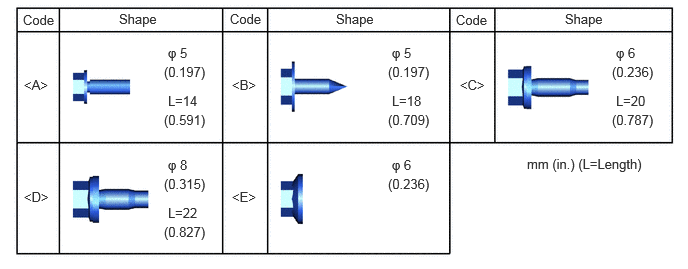 0.24,0.125 0.646,0.396 0.406,0.271 10 false Code 0.25,0.802 0.708,1 0.458,0.198 10 false <A> 0.25,1.969 0.708,2.167 0.458,0.198 10 false <D> 2.417,0.802 2.875,1 0.458,0.198 10 false <B> 4.792,0.802 5.25,1 0.458,0.198 10 false <C> 1.24,0.115 1.74,0.469 0.5,0.354 10 false Shape 1.75,0.469 2.208,0.667 0.458,0.198 10 false φ 5 1.75,0.969 2.208,1.167 0.458,0.198 10 false L=14 2.396,0.115 2.802,0.385 0.406,0.271 10 false Code 3.5,0.115 4,0.469 0.5,0.354 10 false Shape 5.885,0.115 6.385,0.469 0.5,0.354 10 false Shape 4.75,0.125 5.156,0.396 0.406,0.271 10 false Code 2.417,1.969 2.875,2.167 0.458,0.198 10 false <E> 1.708,0.667 2.167,0.865 0.458,0.198 10 false (0.197) 1.708,1.167 2.25,1.448 0.542,0.281 10 false (0.591) 4.083,0.469 4.542,0.667 0.458,0.198 10 false φ 5 4.042,0.667 4.5,0.865 0.458,0.198 10 false (0.197) 4.042,1.167 4.583,1.448 0.542,0.281 10 false (0.709) 4.083,0.969 4.542,1.167 0.458,0.198 10 false L=18 6.417,0.469 6.875,0.667 0.458,0.198 10 false φ 6 6.375,0.667 6.833,0.865 0.458,0.198 10 false (0.236) 6.417,0.969 6.875,1.167 0.458,0.198 10 false L=20 6.375,1.167 6.917,1.448 0.542,0.281 10 false (0.787) 1.75,1.635 2.208,1.833 0.458,0.198 10 false φ 8 1.708,1.833 2.167,2.031 0.458,0.198 10 false (0.315) 4.083,1.635 4.542,1.833 0.458,0.198 10 false φ 6 4.042,1.833 4.5,2.031 0.458,0.198 10 false (0.236) 5.49,1.625 6.781,1.917 1.292,0.292 10 false mm (in.) (L=Length) 1.75,2.135 2.208,2.333 0.458,0.198 10 false L=22 1.708,2.333 2.25,2.615 0.542,0.281 10 false (0.827)
PROCEDURE

 1. PRECAUTION
|
|
|
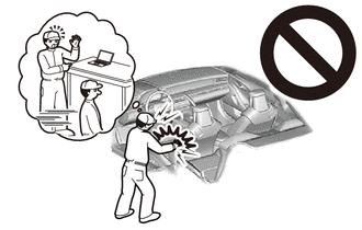
2. CUSTOMIZE POWER TILT AND POWER TELESCOPIC STEERING COLUMN SYSTEM (for Power Tilt and Power Telescopic Steering Column)
|
|
Click here() |
3.ALIGN FRONT WHEELS FACING STRAIGHT AHEAD
4.DISCONNECT CABLE FROM NEGATIVE BATTERY TERMINAL
|
|
|
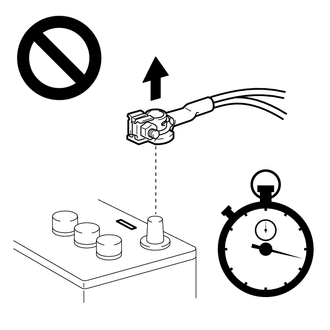
for 1GR-FE:
for V35A-FTS:
5.REMOVE FRONT CONSOLE BOX
w/ Cooler Box:
Click hereVehicle Interior>INTERIOR PANELS / TRIM>FRONT CONSOLE BOX (w/ Cool Box)>REMOVAL
w/o Cooler Box:
Click hereVehicle Interior>INTERIOR PANELS / TRIM>FRONT CONSOLE BOX (w/o Cool Box)>REMOVAL
55606 6.REMOVE NO. 1 INSTRUMENT PANEL UNDER COVER SUB-ASSEMBLY
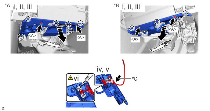
| *A | for LHD | *B | for RHD |
| *C | w/ Interior Illumination Light | - | - |

|
Remove in this Direction (1) |

|
Remove in this Direction (2) |
Remove the 2 screws <A>.
Detach the claw and pull in the removal direction (1) as shown in the illustration.
Pull in the removal direction (2) as shown in the illustration to detach the guide and remove the No. 1 instrument panel under cover sub-assembly.
Detach the clamp.
w/ Interior Illumination Light:
Disconnect the connector.
Using a thin-bladed screwdriver, detach the claw and disconnect the DLC3.
- HINT:
-
Tape the thin-bladed screwdriver tip before use.
55607 7.REMOVE NO. 2 INSTRUMENT PANEL UNDER COVER SUB-ASSEMBLY
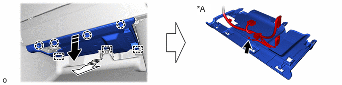
| *A | w/ Interior Illumination Light | - | - |
|
|
Remove in this Direction (1) |
|
Remove in this Direction (2) |
67914B 8.REMOVE FRONT DOOR SCUFF PLATE LH
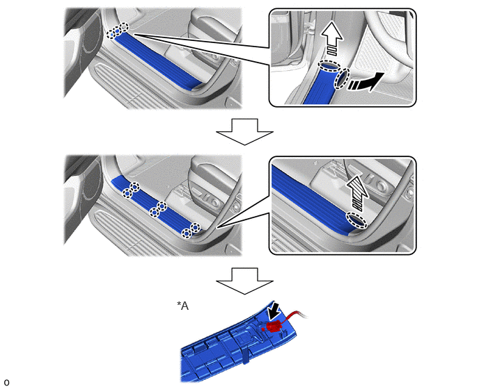
| *A | w/ Interior Illumination Light | - | - |

|
Place Hand Here |
|
Remove in this Direction (1) |
|
|
Remove in this Direction (2) |

|
Remove in this Direction (3) |
67913B 9.REMOVE FRONT DOOR SCUFF PLATE RH
Use the same procedure described for the LH side.
62112 10.REMOVE COWL SIDE TRIM BOARD LH

62111C 11.REMOVE COWL SIDE TRIM BOARD RH
Use the same procedure described for the LH side.
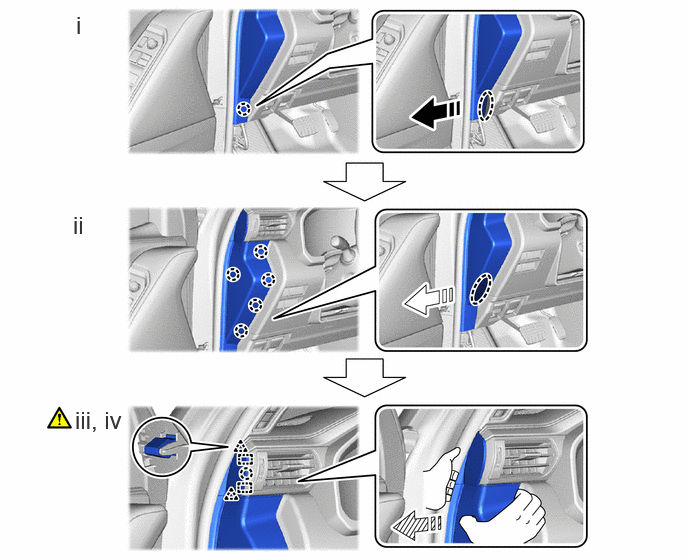
55318F 12.REMOVE NO. 2 INSTRUMENT SIDE PANEL
|
|
Place Hand Here |
|
Remove in this Direction (1) |
|
|
Remove in this Direction (2) |
|
Remove in this Direction (3) |
Place your hands at the position as shown in the illustration, pull in the removal direction (1) and detach the claw.
Place your hands at the position as shown in the illustration, pull in the removal direction (2) and detach the claw.
Place your hand in the gap as shown in the illustration.
Pull in the removal direction (3) as shown in the illustration, detach the clip, claw and guide and remove the No. 2 instrument side panel.
55317E 13.REMOVE NO. 1 INSTRUMENT SIDE PANEL
Use the same procedure described for the No. 2 instrument side panel.
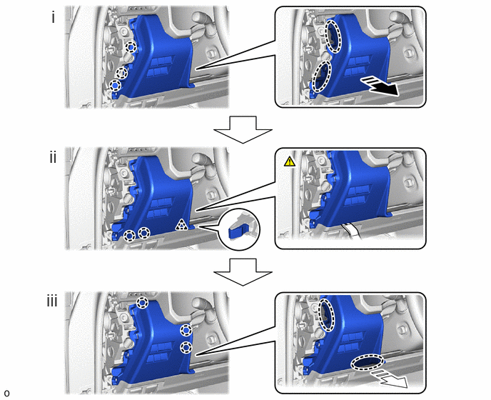
55432D 14.REMOVE LOWER NO. 1 INSTRUMENT PANEL FINISH PANEL
- HINT:
-
The illustrations are representative examples, and details may differ.
|
|
Place Hand Here |
|
Remove in this Direction (1) |
|
|
Remove in this Direction (2) | - | - |
Place your hands at the position as shown in the illustration, pull in the removal direction (1) and detach the claw.
Using moulding remover B, insert the position as shown in the illustration to detach the claw and clip.
Place your hands at the position as shown in the illustration, pull in the removal direction (2) and detach the claw and remove the lower No. 1 instrument panel finish panel.
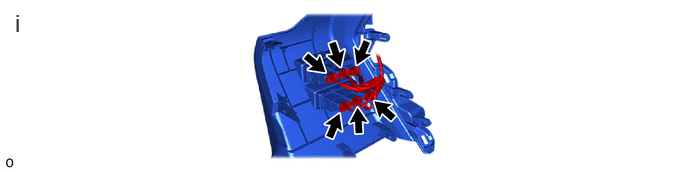
Disconnect each connector.
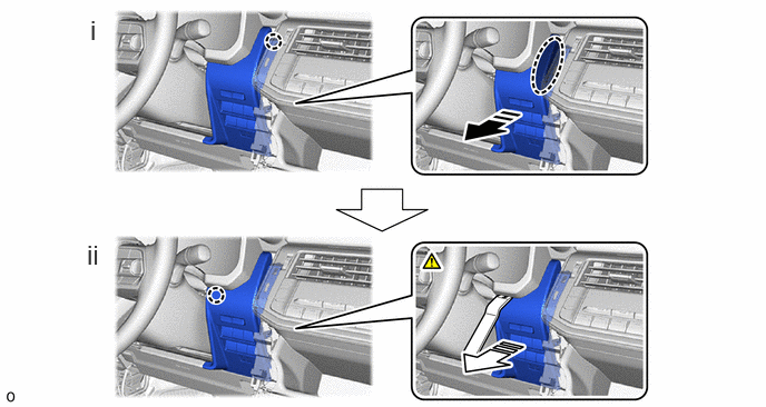
55312 15.REMOVE LOWER INSTRUMENT PANEL
- HINT:
-
The illustrations are representative examples, and details may differ.
|
|
Place Hand Here |
|
Remove in this Direction (1) |
|
|
Remove in this Direction (2) | - | - |
Place your hands at the position as shown in the illustration, pull in the removal direction (1) and detach the claw.
Using moulding remover B, insert the position as shown in the illustration to detach the claw.
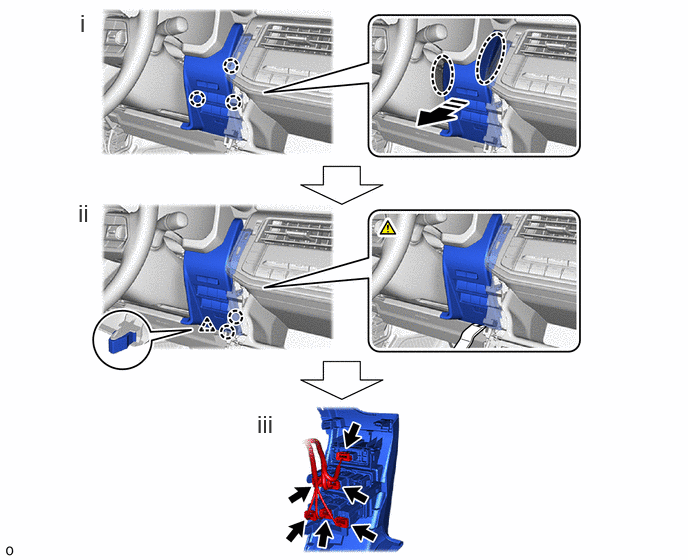
|
|
Place Hand Here |
|
Remove in this Direction |
Place your hands at the position as shown in the illustration, pull in the removal direction (1) and detach the claw.
Using moulding remover B, insert the position as shown in the illustration to detach the claw and clip and lower instrument panel.
Disconnect each connector.
55404D 16.REMOVE INSTRUMENT CLUSTER FINISH PANEL SUB-ASSEMBLY
83100 17.REMOVE COMBINATION METER ASSEMBLY
|
|
Click here() |
55650 18.REMOVE NO. 1 INSTRUMENT PANEL REGISTER ASSEMBLY
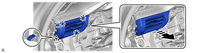
|
|
Remove in this Direction | - | - |
55446A 19.REMOVE NO. 1 SWITCH HOLE BASE
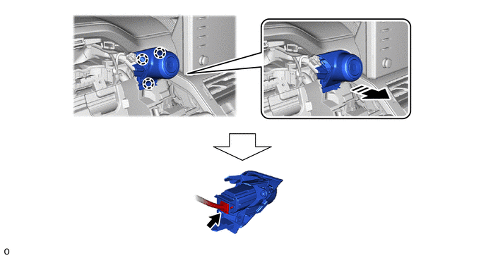
|
|
Remove in this Direction | - | - |
73900 20.REMOVE LOWER NO. 1 INSTRUMENT PANEL AIRBAG ASSEMBLY
|
|
Click here() |
77306 21.REMOVE FUEL LID LOCK OPEN LEVER SUB-ASSEMBLY
53601 22.REMOVE HOOD LOCK CONTROL LEVER SUB-ASSEMBLY
73990 23.REMOVE LOWER NO. 2 INSTRUMENT PANEL AIRBAG ASSEMBLY
|
|
Click here() |
55443A 24.REMOVE INSTRUMENT PANEL BOX DOOR COVER
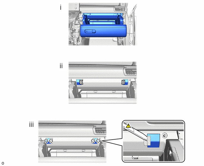
Open the glove compartment door sub-assembly.
Apply the protective tape as shown in the illustration.
Using moulding remover E, detach the claw and remove the 2 instrument panel box door covers.
55320 25.REMOVE LOWER NO. 2 INSTRUMENT PANEL ASSEMBLY
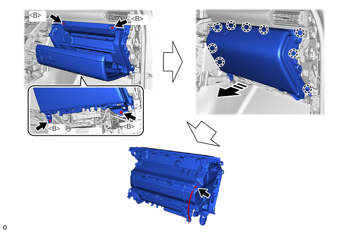
|
|
Remove in this Direction | - | - |
55660 26.REMOVE NO. 2 INSTRUMENT PANEL REGISTER ASSEMBLY
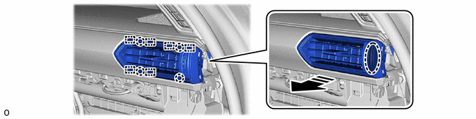
|
|
Place Hand Here |
|
Remove in this Direction |
74617A 27.REMOVE ASSIST GRIP PLUG
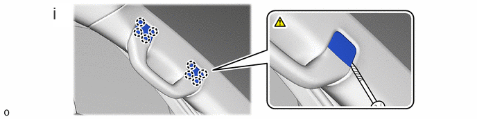
Using a thin-bladed screwdriver, detach the claw and remove the 2 assist grip plugs.
- HINT:
-
·
Tape the thin-bladed screwdriver tip before use.
·Use the same procedure described for the opposite side.
74620G 28.REMOVE FRONT ASSIST GRIP ASSEMBLY
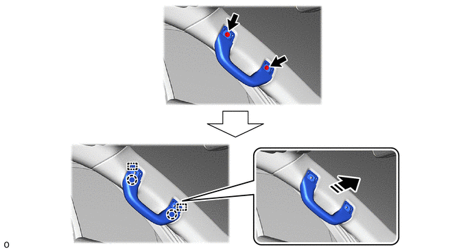
|
|
Remove in this Direction | - | - |
- HINT:
-
Use the same procedure described for the opposite side.
62212B 29.REMOVE FRONT PILLAR GARNISH ASSEMBLY LH
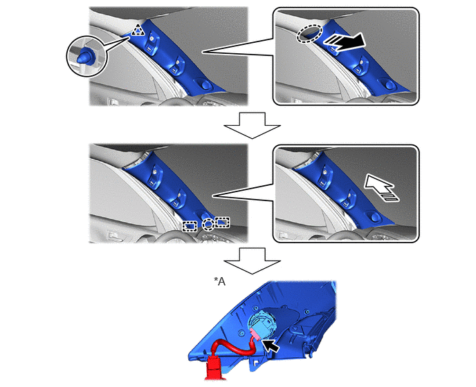
| *A | for 14 Speakers | - | - |
|
|
Place Hand Here |
|
Remove in this Direction (1) |
|
|
Remove in this Direction (2) | - | - |
w/ Curtain Shield Airbag:
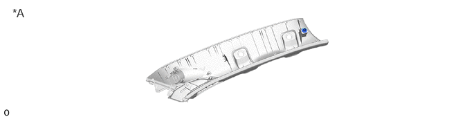
| *A | When reusing a front pillar garnish assembly LH | - | - |
62211U 30.REMOVE FRONT PILLAR GARNISH ASSEMBLY RH
Use the same procedure described for the LH side.
55408F 31.REMOVE NO. 1 INSTRUMENT PANEL SPEAKER PANEL SUB-ASSEMBLY
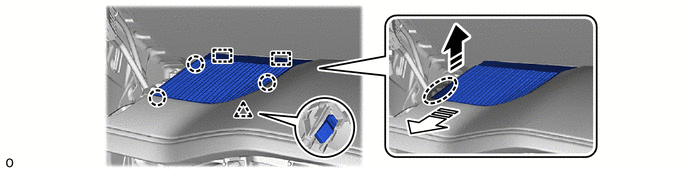
|
|
Place Hand Here |
|
Remove in this Direction (1) |
|
|
Remove in this Direction (2) | - | - |
55409F 32.REMOVE NO. 2 INSTRUMENT PANEL SPEAKER PANEL SUB-ASSEMBLY
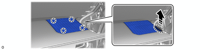
|
|
Place Hand Here |
|
Remove in this Direction |
55423B 33.REMOVE INSTRUMENT CLUSTER FINISH PANEL COVER (w/o Multi-display)
for Type A:
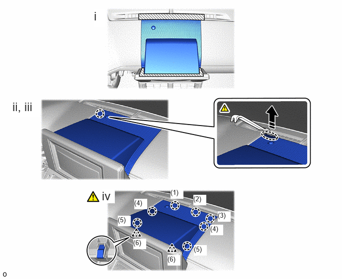
|
|
Place Hand Here |
|
Remove in this Direction |
Apply the protective tape as shown in the illustration.
Using moulding remover B, insert the position as shown in the illustration.
Place your hand in the gap as shown in the illustration and detach the claw.
Detach the claw and clip in the order shown in the illustration and remove the instrument cluster finish panel cover.
for Type B:
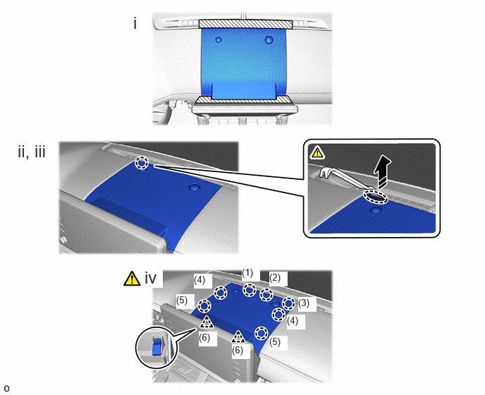
|
|
Place Hand Here |
|
Remove in this Direction |
Apply the protective tape as shown in the illustration.
Using moulding remover B, insert the position as shown in the illustration.
Place your hand in the gap as shown in the illustration and detach the claw.
Detach the claw and clip in the order shown in the illustration and remove the instrument cluster finish panel cover.

Disconnect the connector.
55510F 34.REMOVE NO. 1 SPEAKER OPENING COVER ASSEMBLY (w/ Multi-display)
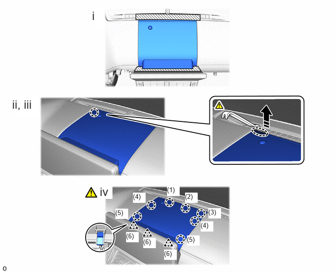
|
|
Place Hand Here |
|
Remove in this Direction |
Apply the protective tape as shown in the illustration.
Using moulding remover B, insert the position as shown in the illustration.
Place your hand in the gap as shown in the illustration and detach the claw.
Detach the claw and clip in the order shown in the illustration and remove the No. 1 speaker opening cover assembly.

Disconnect the connector.
55981 35.REMOVE NO. 1 DEFROSTER NOZZLE GARNISH
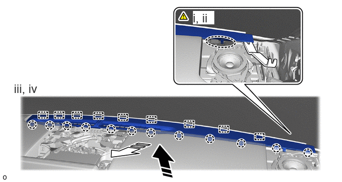
|
|
Place Hand Here |
|
Remove in this Direction (1) |
|
|
Remove in this Direction (2) | - | - |
Using moulding remover B, insert the position as shown in the illustration.
Place your hand in the gap as shown in the illustration.
Pull in the removal direction (1) as shown in the illustration and detach the claw.
Pull in the removal direction (2) as shown in the illustration, detach the guide and remove the No. 1 defroster nozzle garnish.
36.REMOVE AIR CONDITIONING PANEL ASSEMBLY
55422C 37.REMOVE CENTER UPPER INSTRUMENT CLUSTER FINISH PANEL (w/o Audio)
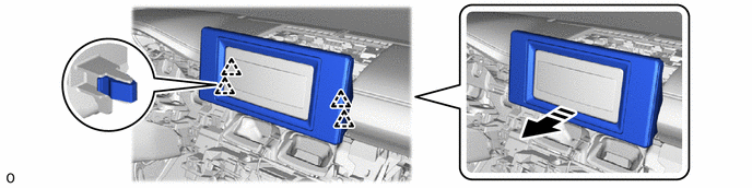
55522B 38.REMOVE RADIO TUNER OPENING COVER (w/o Audio)

39.REMOVE RADIO RECEIVER ASSEMBLY WITH BRACKET (w/ Audio, for Radio Receive Type)
40.REMOVE RADIO AND DISPLAY RECEIVER ASSEMBLY WITH BRACKET (w/ Audio, for Radio and Display Type)
86110B 41.REMOVE MULTI-DISPLAY ASSEMBLY (w/ Audio, Multi-display)
55406B 42.REMOVE CENTER LOWER INSTRUMENT CLUSTER FINISH PANEL SUB-ASSEMBLY (w/o Multi-display)
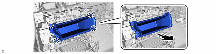
|
|
Remove in this Direction | - | - |
55414A 43.REMOVE INSTRUMENT CLUSTER FINISH PANEL END (w/ Headup Display)
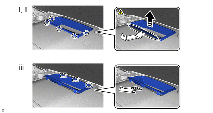
|
|
Place Hand Here |
|
Remove in this Direction (1) |
|
|
Remove in this Direction (2) | - | - |
Using moulding remover B, insert the position as shown in the illustration.
Place your hand in the gap as shown in the illustration, detach the claw.
Detach the guide and remove the instrument cluster finish panel end as shown in the illustration.
86160J 44.REMOVE FRONT NO. 3 SPEAKER ASSEMBLY (except 2 Speakers, for Side)
|
|
|
86160L 45.REMOVE FRONT NO. 4 SPEAKER ASSEMBLY (w/ Multi-display, for Center)
|
|
Click here() |
45100 46.REMOVE STEERING WHEEL ASSEMBLY
45024 47.REMOVE LOWER STEERING COLUMN COVER SUB-ASSEMBLY
|
|
Click here() |
45286B 48.REMOVE UPPER STEERING COLUMN COVER
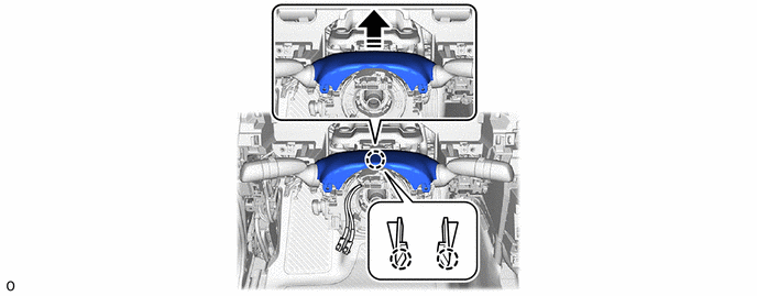
|
|
Remove in this Direction | - | - |
84650 49.REMOVE WINDSHIELD WIPER SWITCH ASSEMBLY
|
|
Click here() |
50.REMOVE FLOOR SHIFT LEVER ASSEMBLY (w/ Telematics Transceiver)
|
|
·
for AC60F: Click here(
·
for AJA0F: Click here( |
58123A 51.REMOVE SHIFT AND SELECT LEVER SUPPORT (w/ Telematics Transceiver)
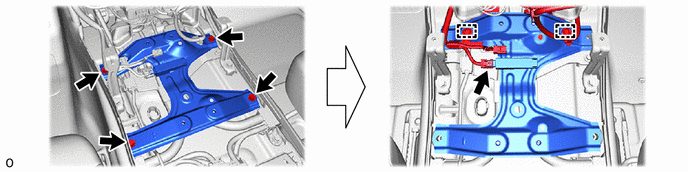
52.REMOVE INSTRUMENT PANEL SAFETY PAD ASSEMBLY
w/ Telematics Transceiver:
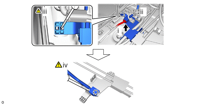
Disconnect the connector.
Detach the clamp.
Using a thin-bladed screwdriver, detach the clamp.
- HINT:
-
Tape the thin-bladed screwdriver tip before use.
Using a thin-bladed screwdriver, detach the claw and disconnect the wire harness.
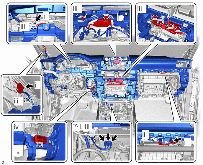
| *A | w/ Telematics Transceiver | - | - |

|
Connector |

|
Airbag Connector |
Disconnect each connector.
Disconnect the airbag connector.
- HINT:
-
Refer to How to Connect or Disconnect Airbag Connector:
Detach the clamp.
Detach the guide.
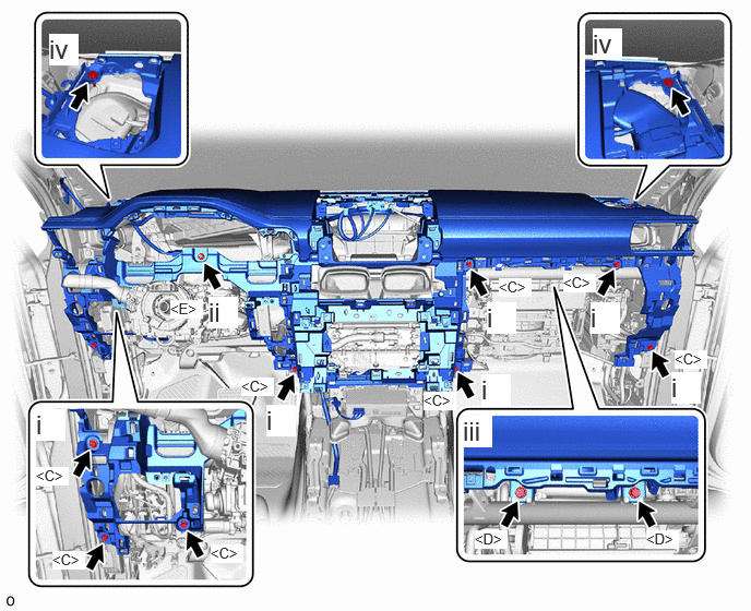
Remove the 8 bolts <C>.
Remove the nut <E>.
Remove the 2 bolts <D>.
Remove the 2 clips.
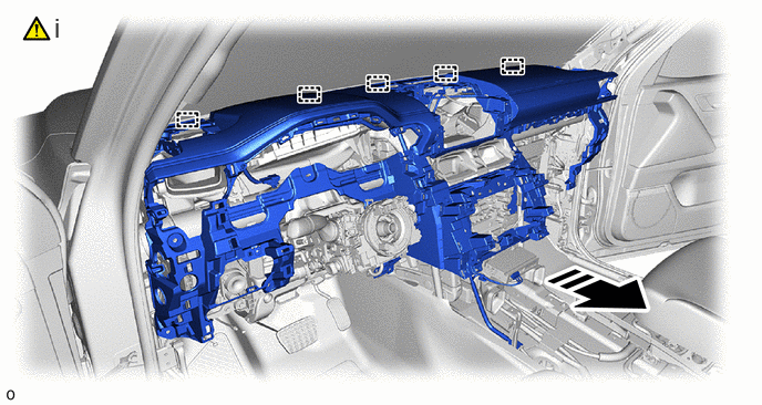
|
|
Remove in this Direction | - | - |
Detach the guide as shown in the illustration.
- NOTICE:
-
·
Do not damage the instrument panel safety pad assembly or vehicle interior.
·Make sure that the wire harness does not get caught on anything as it may become damaged.
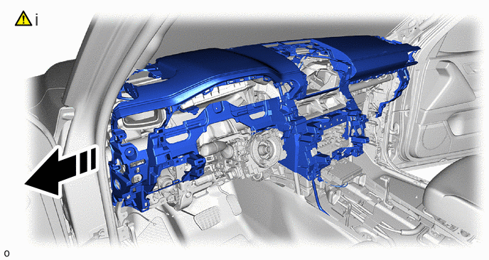
|
|
Remove in this Direction | - | - |
Remove the instrument panel safety pad assembly as shown in the illustration.
- NOTICE:
-
·
Do not damage the instrument panel safety pad assembly or vehicle interior.
·Make sure that the wire harness does not get caught on anything as it may become damaged.